935CA: Installation, Start-up, Operating and Service and Maintenance Instructions
Manufacturer reserves the right to change, at any time, specifications and designs without notice and without obligations.
33
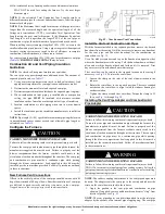
A13406
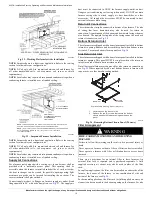
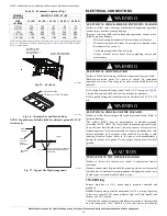
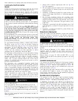
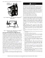
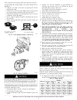
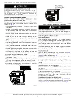
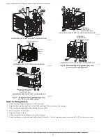
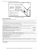
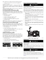
Fig. 48 – Combustion Air Pipe Attachment
Size the Vent and Combustion Air Pipes
General
Furnace combustion air and vent pipe connections are sized for 2-in. (50
mm ND) PVC/ABS DWV pipe. The combustion air and vent pipe
connections also accommodate 60 mm polypropylene venting systems
with outside diameters of approximately 60 mm (2-3/8 inches). Any pipe
diameter change should be made outside furnace casing in vertical pipe.
Any change in diameter to the pipe must be made as close to the furnace
as reasonably possible, see
Fig. 51
.
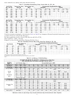
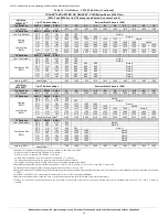
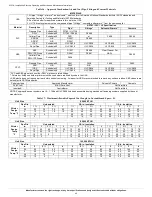
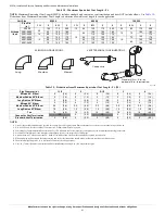
The Maximum Vent Length for the vent and combustion air pipe (when
used) is determined from the Maximum Equivalent Vent Length
(
Table 18
) minus the number of fittings multiplied by the deduction for
each type of fitting used, see
Table 19
.
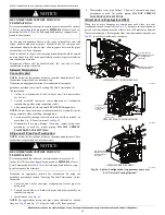
A200089
NOTE:
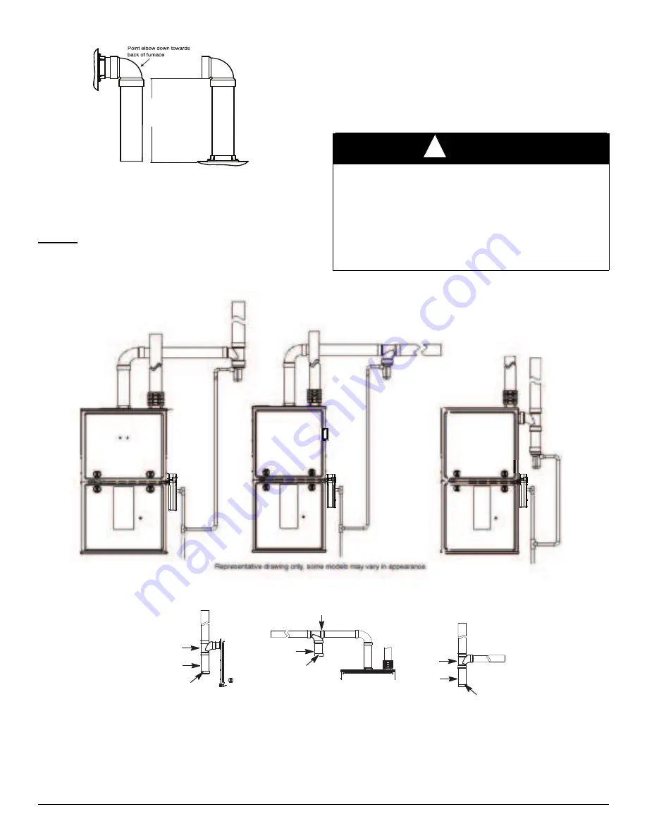
Only connect combustion air inlet moisture drain downstream of the furnace trap assembly as shown.
A200366
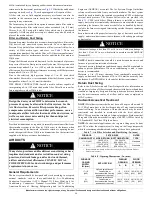
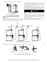
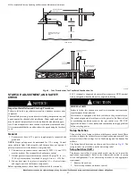
Fig. 49 – Recommended Combustion Air Inlet Moisture Trap
12" (256mm) minimum
to
60”(1524 mm) or
1 additional elbow maximum
CASING SIDE OR TOP ATTACHMENT
COMBUSTION AIR PIPE
(NON-DIRECT VENT FOR ALL MODELS EXCEPT MODULATING UNLESS
INSTALLED IN ATTIC OR CRAWL SPACE)
NOTICE
!
OPTIONAL CONFIGURATION FOR COMBUSTION AIR INLET
PIPE
In applications where there is a risk of excessive moisture entering the
combustion air inlet pipe, a moisture trap may be added to the inlet pipe
to help prevent moisture from entering the furnace from the combustion
air inlet pipe, see
Fig. 49
.
When sizing venting systems, the equivalent length of the optional
moisture trap (15 feet/5 M) must be taken into account.
Representative drawing only, some models may vary in appearance.
Tee
Dry Well
Cap
(water tight
and removable)
Tee
Dry Well
Cap
(water tight
and removable)
Tee
Dry Well
Cap
(water tight
and removable)

