935CA: Installation, Start-up, Operating and Service and Maintenance Instructions
Manufacturer reserves the right to change, at any time, specifications and designs without notice and without obligations.
48
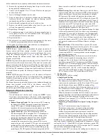
3. Configure the setup switches as necessary for the application.
4. Replace blower door.
NOTE:
If a bypass humidifier is used, setup switch SW1-4
(Comfort/Efficiency) should be in OFF=Efficiency position. This
compensates for the increased temperature in return air resulting from
bypass.
NOTE:
If modulating dampers are used, blower motor automatically
compensates for modulating dampers.
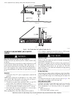
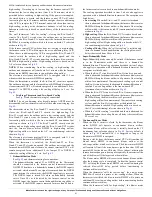
Air Conditioning (A/C) Setup Switches (SW2)
The air conditioning setup switches are used to match furnace airflow to
required cooling airflow or high stage cooling airflow when a two-stage
outdoor unit is used. Refer to the Adjustments section for setup switch
configurations.
To set the desired cooling airflow:
1. Remove blower door.
2. Locate A/C setup switches on furnace control.
3. Determine air conditioning tonnage used.
4. Configure the switches for the required cooling airflow.
5. Replace blower door.
NOTE:
Incorrect airflow caused by improper A/C switch setup may
cause condensate blow-off or a frozen indoor coil in cooling mode.
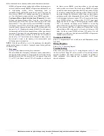
Continuous Fan (CF) Setup Switches (SW3)
The CF setup switches are used to select desired airflow when
thermostat is in continuous fan mode or to select low-cooling airflow for
two-speed cooling units. Refer to the Adjustments section for setup
switch configurations. To set desired cooling airflow:
1. Remove blower door.
2. Locate CF setup switches on furnace control.
3. Determine air conditioning tonnage used for low cooling (when
used) or desired continuous fan airflow.
4. Configure the switches for the required airflow.
5. Replace blower door.
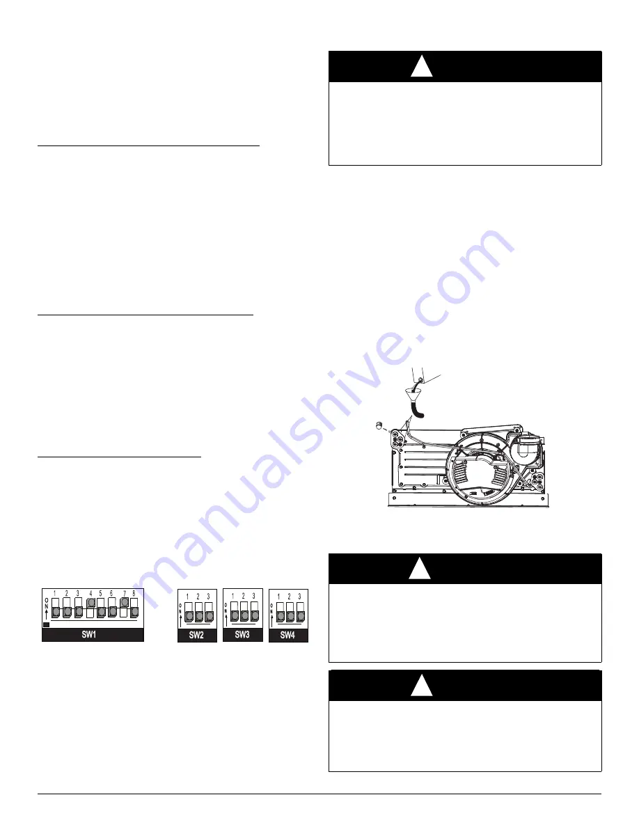
Additional Setup Switches (SW4)
The furnace control has three additional setup switches labeled SW4.
Setup switches SW4 are used for applications using a communicating
User Interface and to adjust airflow. SW4-3 is used to adjust airflow.
Refer to the Adjustments section for setup switch configurations. Refer
to User Interface instructions for other SW4 switch configurations.
1. Remove blower door.
2. Locate setup switch SW-4 on furnace control.
3. Configure the switches as necessary for the application.
4. Replace blower door.
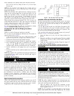
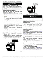
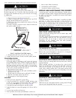
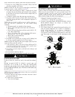
A200340
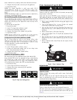
Fig. 65 – Dip Switch Configuration
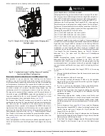
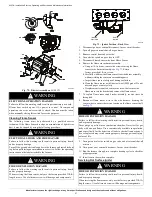
Prime Condensate Trap with Water
1. Remove upper and middle collector box drain plugs opposite of the
condensate trap.
2. Connect field-supplied 5/8-in. (16 mm) ID tube with attached
funnel to upper collector box drain connection.
3. Pour one quart (liter) of water into funnel/tube. Water should run
through collector box, overfill condensate trap, and flow into open
field drain.
4. Remove funnel; replace collector box drain plug.
5. Connect field-supplied 5/8-in. (16 mm) ID tube to middle collector
box drain port.
6. Pour one quart (liter) of water into funnel/tube. Water should run
through collector box, overfill condensate trap, and flow into open
field drain.
7. Remove funnel and tube from collector box and replace collector
box drain plug.
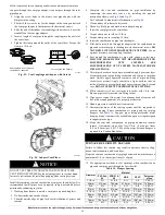
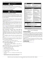
A190304
Fig. 66 – Prime Condensate Trap
Adjustments
CAUTION
!
UNIT OPERATION HAZARD
Failure to follow this caution may result in intermittent unit operation
or performance satisfaction.
Condensate trap must be PRIMED or proper draining may not occur.
The condensate trap has two internal chambers which can ONLY be
primed by pouring water into the inducer drain side of condensate trap.
WARNING
!
FIRE HAZARD
Failure to follow this warning could result in injury, death and/or
property damage.
DO NOT bottom out gas valve regulator adjusting screw. This can
result in unregulated gas valve outlet pressure and result in excess
overfire and heat exchanger failures.
CAUTION
!
FURNACE DAMAGE HAZARD
Failure to follow this caution may result in reduced furnace life.
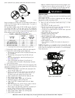
DO NOT redrill orifices. Improper drilling (burrs, out-of-round holes,
etc.) can cause excessive burner noise and misdirection of inlet gas, see
Fig. 67
)

