background image

5

S

Do not cover the furnace, store trash or debris near it, or in any
way block the

fl

ow of fresh air to the unit.

In addition to the safety rules above, make sure that the following

combustion--air requirements are met for non--direct vent
applications:

S

Combustion air must be clean and uncontaminated with chlorine
or fluorine. These compounds are present in many products
around the home, such as: water softener salts, laundry bleaches,
detergents, adhesives, paints, varnishes, paint strippers, waxes,
and plastics.

S

Make sure the combustion air for your furnace does not contain
any of these compounds. During remodeling be sure the
combustion air is fresh and uncontaminated. If these compounds
are burned in your furnace, the heat exchangers may deteriorate.

S

A furnace installed in an attic or other insulated space must be
kept free and clear of insulating material. Examine the furnace
area when the furnace is installed or when insulation is added.
Some insulation materials may be combustible.

S

Should the gas supply fail to shut off or if overheating occurs,
shut off the gas valve to the furnace before shutting off electrical
supply.

This furnace contains SAFETY DEVICES which must be

MANUALLY RESET. If the furnace is left unattended for an
extended period of time, have it checked periodically for proper

operation. This precaution will prevent problems associated with

no heat, such as frozen water pipes, etc. See “Before You Request
a Service Call” section in this manual.

FIRE OR EXPLOSION HAZARD

Failure to follow this warning could result in personal injury,

death, or property damage.
Do not keep combustible materials, gasoline, and other

flammable liquids or vapors around your furnace.

!

WARNING

UNIT OPERATION HAZARD

Failure to follow this caution may result in intermittent unit

operation.
For proper and safe operation the furnace needs air for

combustion and ventilation. Do not block or obstruct air

openings on the furnace, air opening to the area in which the

furnace is installed, and the space around the furnace.

CAUTION

!

BEFORE STARTING YOUR FURNACE

Examine the furnace installation to determine that:

1. All flue gas carrying areas external to the furnace (i.e. chim-

ney, vent connector) are clear and free of obstructions.

2. The vent connector is in place, slopes upward and is physic-

ally sound without holes or excessive corrosion.

3. The return--air duct connection(s) is physically sound, is

sealed to the furnace casing, and terminates outside the

space containing the furnace.

4. The physical support of the furnace is sound without sag-

ging cracks, gaps, etc. around the base.

5. There are no obvious signs of deterioration of the furnace.
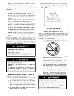
6. The burner flames are in good adjustment, See Fig. 4 (by

comparison with pictorial sketches or drawings of the main
burner flame).

A92330

Fig. 4 -- Burner Flame Adjustment

STARTING YOUR FURNACE

Instead of a continuously burning pilot flame which wastes

valuable energy, your furnace uses an automatic, hot surface

ignition system to light the burners each time the thermostat signals
the furnace to start.

Follow these important safeguards:

S

Never attempt to manually light the burners with a match
or other source of flame. See Fig. 5.

A92319

Fig. 5 -- Do Not Light Burner with Match

S

Read and follow the operating instructions on inside of
main furnace door, especially the item that reads as fol-

lows:
“Wait 5 minutes to clear out any gas. Then smell for gas,

including near the floor. If you smell gas,

STOP!

Fol-

low “B” in the safety information on furnace label. If you
don’t smell gas, go to the next step.”

S

If a suspected malfunction occurs with your gas control
system, such as the burners do not light when they

should, refer to the shutdown procedures on inside of
main furnace door, or in the “Shutting Down Your Fur-

nace” section and call your dealer as soon as possible.

FIRE AND EXPLOSION HAZARD

Failure to follow this warning could result in personal injury,

death or property damage.
Should the gas supply fail to shut off or if overheating occurs,

turn off the manual gas valve to the furnace BEFORE turning

off the electrical supply and install lockout tag.

!

WARNING

Summary of Contents for Condencing Gas Furnace

Page 1: ...ified installer service agency or the gas supplier WARNING CARBON MONOXIDE POISONING HAZARD Failure to follow this warning could result in personal injury and or death Carbon Monoxide is invisible odorless and toxic Install a carbon monoxide alarm in your home even if you do not own a gas appliance Locate the carbon monoxide alarm in the living area of your home and away from gas appliances and do...

Page 2: ...your new furnace is so efficient over 90 of the heat generated during combustion is captured and delivered inside your home That is more than a 30 increase in heating efficiency over conventional furnaces This furnace is among the safest most dependable energy efficient furnaces you can buy today We are proud of the technological advances incorporated into the design of this furnace With only mini...

Page 3: ...vary 9 Condensate drain connection collects moisture condensed from burned gases for disposal into home drain system location in furnace varies 10 Heavy duty blower circulates air across the heat ex changers to transfer heat into the home 11 Secondary condensing heat exchanger inside Wrings out more heat through condensation Constructed with polypro pylene laminated steel to ensure durability 12 P...

Page 4: ...nt 2 pipe Fig 1 application or as a non direct vent 1 pipe Fig 2 application S In a direct vent 2 pipe application your furnace uses air from outside the home for combustion and vents flue gas to the outdoors This type of application will have 2 pipes running from the furnace to the outdoors See Fig 1 In this application the vent and air intake pipes must terminate outside the structure and must n...

Page 5: ...e area in which the furnace is installed and the space around the furnace CAUTION BEFORE STARTING YOUR FURNACE Examine the furnace installation to determine that 1 All flue gas carrying areas external to the furnace i e chim ney vent connector are clear and free of obstructions 2 The vent connector is in place slopes upward and is physic ally sound without holes or excessive corrosion 3 The return...

Page 6: ...Fig 8 A92185 Fig 8 Turn Off Electrical Supply 4 Remove the main furnace door See Fig 9 A05087 Fig 9 Remove Furnace Door 5 Turn the control switch on the gas control to the OFF position and wait 5 minutes See Fig 10 Then smellfor gas including near the floor If you smell gas STOP Follow B on furnace label If you don t smell gas go to next step GAS CONTROL SWITCH SHOWN IN OFF POSITION TWO STAGE GAS ...

Page 7: ...ely cold days The few de grees at the top of your thermostat comfort level are the most costly degrees to obtain When the room temperature drops below the temperature selected on the thermostat the furnace will switch on automatically When the room temperature reaches the setting selected on the thermostat the furnace will be automatically switched off Continuous Fan Operation Some thermostats hav...

Page 8: ...e hazardous due to gas and electrical components Only trained and qualified personnel should install repair or service heating equipment Untrained personnel can perform basic maintenance functions such as cleaning and replacing air filters All other operations must be performed by trained service personnel Observe safety precautions in this manual on tags and on labels attached to the furnace and ...

Page 9: ...See Fig 25 d Slide air filter out of furnace See Fig 26 S AIR FILTER S LOCATED IN BLOWER COMPARTMENT SIDE a Remove filter retainer from latch See Fig 27 b Gently remove air filter and carefully turn the dirty side up if dirty to avoid spilling dirt from the filter See Fig 28 S AIR FILTER S LOCATED IN FILTER CABINET a Remove filter cabinet door See Fig 23 and 24 NOTE It will be necessary to remove ...

Page 10: ...wer Cabinet A93010 Fig 25 Release Filter Retaining Rod Bottom Inlet A93011 Fig 26 Slide Filter Out Bottom Inlet A93012 Fig 27 Release Filter Retaining Rod Side Inlet A93013 Fig 28 Slide Filter Out of Furnace Side Inlet A00227 Fig 29 Removal of Filter from Side Blower Cabinet A00228 Fig 30 Removal of Filter from Bottom Blower Cabinet ...

Page 11: ... 21 533 1 16 x 25 x 3 4 406 x 635 x 19 1 20 x 25 x 3 4 508 x 635 x 19 3 4 19 mm thick washable 24 1 2 610 1 16 x 25 x 3 4 406 x 635 x 19 1 24 x 25 x 3 4 610 x 635 x 19 3 4 19 mm thick washable Table 2 Air Filter Located in Filter Cabinet FILTER CABINET HEIGHT IN MM FILTER SIZE IN MM FILTER TYPE 16 406 1 16 x 25 x 3 4 406 x 635 x 19 or 1 16 x 25 x 4 5 16 406 x 635 x 110 washable 20 508 1 20 x 25 x ...

Page 12: ...he combustion air intake adjacent to the furnace or outside your home for blockage Also check the vent pipe on the outside of your home for blockage NOTE If your furnace makes a loud noise when the main burners are ignited shut down the furnace and call your servicing dealer Use your flashlight and follow these steps for inspecting the combustion area and vent system of your furnace CARBON MONOXID...

Page 13: ...or equivalent UNIT COMPONENT DAMAGE HAZARD Failure to follow this caution may result in damage to the furnace and other property damage Do not use ethylene glycol Prestone II antifreeze coolant or equivalent Failure of plastic components may occur CAUTION 2 Turn off electrical supply to your furnace 3 Remove main furnace door 4 Remove upper inducer housing drain connection cap See Fig 38 5 Connect...

Page 14: ...mostat for proper temperature Is thermostat set above room temperature S Is thermostat set to HEAT mode S Check fuses and circuit breakers Is the electrical power supply switch on S Is the manual shut off valve in the gas supply pipe leading to the furnace open NOTE Turn off electrical supply before continuing with checklist S Is control switch on gas valve in ON position Follow start up procedure...

Page 15: ...ial _____________________________________ INDOOR COIL Furnace Coil or Fan Coil Model _____________________________________ Serial _____________________________________ INSTALLATION INFORMATION Date Installed ________________________________ DEALERSHIP CONTACT INFORMATION Company Name_______________________________ Address______________________________________ ______________________________________...

Page 16: ...e or change at any time specifications or designs without notice and without incurring obligations E2009 Bryant Heating Cooling Systems D 7310 W Morris St D Indianapolis IN 46231 Printed in U S A Edition Date 09 09 Replaces OM05 56 Catalog No OM05 58 ...

Reviews: