
10
BLK
B
LA
C
K
BL
U
B
LU
E
BR
N
B
RO
WN
GRN
G
R
EE
N
GR
Y
G
RY
ORG
O
R
A
N
G
E
RE
D
R
ED
WH
T
W
H
IT
E
Y
E
L
Y
ELL
OW
CO
LO
R CO
D
E
Ca
ra
ct
ér
is
ti
q
u
e
c
ritiqu
e
C
ritical
char
ac
te
rist
ic
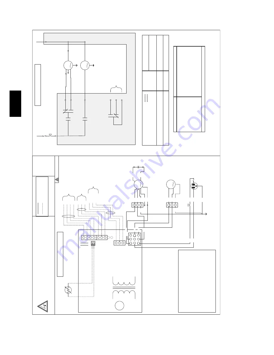
CO
NNEC
TION DIA
GRAM
1
2
3
4
5
6
7
8
9
1
2
3
3
4
5
6
7
8
9
J3
J2
J1
J4
F
F
I
OC
OL
B
R
Y
G
FAN MO
TO
R
DA
M
PE
R M
O
TO
R
120V
, 60H
z
NEM
A-15P
5-15 PL
U
G
(n
ote
4
)
MO
TO
R
CAP
A
CIT
O
R
BRN
BR
N
BL
U
RED
BL
U
BL
U
WHT
NC
GR
Y
OR
G
BL
U
YEL
BL
K
WH
T
-t
DEFROST TEMPERA
TU
RE
SE
NS
OR
(C
O
M
M
O
N
)
(NO C
O
NT
AC
T)
(NC C
O
NT
AC
T)
BL
K
GRN
RED
YEL
RED
BL
K
YEL
W
ALL C
O
NTROL
NO
TE 1
OVERRIDE
OPT
ION
AL
C
onnec
t t
o
G on F
u
rnac
e/F
an c
o
il
C
onnec
t t
o
G on
Thermostat
C
onnec
t t
o
R on F
u
rnac
e/F
an c
oil
ME
D
LO
NEUTRAL
FA
N MO
TO
R
DA
M
PE
R M
O
TO
R
HI
LO
K5
REL
AY
K1
REL
AY
K2
RE
LA
Y
K3
RE
LA
Y
ME
D
J1
-4
J1
-6
J1
-9
J3
-2
J3
-1
J1
-3
J1
-1
J1
-8
J1
-2
12
0V
, 60H
z RE
TU
RN
AIR HA
NDL
E
R
FA
N
INT
ERL
OCK
24
V
A
C
CL
ASS 2
CIRCUIT
ONL
Y
LO
GIC DIA
GRAM
LINE VOL
TA
GE
CLASS
2
LO
W
VOL
TA
G
E
AN
D FIEL
D
WIRING
G
ABC
DEF
RED
3
2
1
HI
ORG
GR
Y
GRN
3
2
1
GRN
GRN
GRN
GRN
WA
RN
IN
G
ELEC
TRICAL
SH
OC
K HA
ZA
RD
Disco
n
ne
ct
p
o
w
e
r
bef
o
re
ser
vicing /
m
aint
e
na
nc
e or
field wiri
ng
. Reinst
all
al
l
pa
ne
ls bef
o
re
o
per
at
in
g
. F
ail
ur
e
to
do
so
can
r
e
sult
in
de
ath
or e
lec
trical sho
ck
.
AV
ER
TIS
SEMENT
RISQUE DE CHOC ÉL
EC
TR
IQ
UE
Débran
ch
ez la sour
ce
d'a
lim
entation
éle
ctriq
ue a
van
t
l'en
tr
etien
, l
a
ré
pa
ra
tion
ou
le r
ac
co
rd
e
men
t su
r
pla
ce .
Re
plac
e
z t
o
us les
pan
n
ea
ux
avant d
'utiliser
. L
e
no
n-
re
spec
t de
ces
instruc
ti
o
ns peut caus
er un décès ou
un
cho
c éle
ctr
iq
ue
ADVERTENCIA
PELIG
RO
DE CHOQUE E
LÉC
TR
IC
O
Desco
n
ec
te
e
l sumi
n
istr
o
de
en
er
g
ía
an
tes de r
e
par
ar
, de ma
nt
e
n
e
r
o
de
ca
b
le
ar in
sit
u
. V
u
e
lv
a a
co
locar t
o
do
s
los p
an
e
les a
n
te
s de
ha
ce
r lo
fu
ncion
ar
. No se
gu
ir
e
stas
instruc
cio
nes
pued
e
causar la muer
te
o
ch
oq
ue
el
éc
tr
ic
o
.
NO
TES
1-
C
O
NTROLS A
V
AILABLE SEE
THE INSTRUC
TION M
A
NU
AL
2-
IF AN
Y OF
THE ORIGINAL
WIRE AS SUPPLIED MUST B
E
REPLA
CED
, USE
THE SAME OR EQUIV
ALENT
WIRE.
3-
FA
C
TOR
Y SE
T
WIRING FOR BL
OWER SPEED IS HIGH AND
L
O
W SPEED
. MEDIUM SPEED CAN BE SELEC
TED INSTEAD OF
L
O
W SPEED
. DISC
ONNEC
T
RED
WIRE FROM MO
TO
R(S) RED
T
AP AND
C
O
NNEC
T
TO
MO
TOR(S) BL
UE
TA
P.
4-
US
E SPECIFIED UL LISTED
/CSA CER
T
IFIED LINE FUSE
.
FOR ALL U
N
ITS:
LIT
TELFUSE (225 00
3), 2A
G F
A
ST
-A
C
T
ING FU
SE,
224/225
SERIES, RA
TI
NG: 3 A
F
Door int
e
rl
o
ck
swit
ch
J1-
3
120
V, 60H
z LIN
E
F
BL
K
D
e
fr
os
t c
y
cl
es
(m
inut
es
)
(D
e
fr
o
st
/
v
e
n
til
at
io
n
)
3
2
E
L
B
A
T
R
E
P
M
UJ
°
F5
°
F-
1
7
°
F
JU
1
-A
JU1
-B
JU
1
-C
JU1
-D
JU
1
-E
JU1
-F
JU
1
-G
M
O
D
E
L
-5
°
C-
1
5
°
C-
2
7
°
C
IN
O
U
T
O
U
T
IN
IN
IN
O
U
T
E
R
V
B
B
LH
A
1
1
5
0
1
0
/6
0
1
0
/3
0
1
0
/2
0
IN
O
U
T
O
U
T
IN
IN
IN
O
U
T
E
R
V
BBLH
A
120
0
1
0/
6
0
10
/3
0
1
0
/20
IN
O
U
T
O
U
T
IN
IN
O
U
T
O
U
T
Ex
ten
d
ed def
ros
t al
l
mo
d
el
s
1
0
/30
1
0
/2
0
1
0/
1
5
G
AB
CD
EF
FUNC
T
ION T
A
BLE
R
ELA
Y
MODE
K
1
K2
K3
K5
In
te
rmitt
ent (2
0 min per hour)
0
0
0
1
Ex
change L
o
w
1
0
1
0
Ex
change H
ig
h
1
1
1
0
Cir
culation L
o
w
1
0
1
1
Cir
culation H
igh
1
1
1
1
1
1
1
1
el
c
y
C t
s
orf
e
D
1
0
0
0
F
F
O
0 = Rela
y c
o
il is de
-e
ner
g
iz
ed
1 = Rela
y c
o
il is ener
g
iz
e
d
A
09191
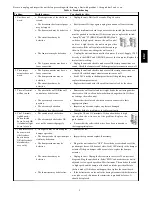
Fi
g.
12
--
ER
V
W
ir
in
g
D
iagr
am
ER
V


