4
BLACK
CONTROL
CONNECTOR
OL
OC
IY
R
G
B
GREEN
RED
YELLOW
A07611
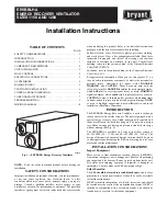
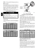
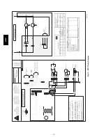
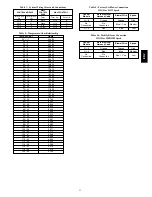
Fig. 8 -- Control Connector
Operation
The ERV wall control has 4 basic modes of operation, OFF, LOW,
HIGH, and INTERMITTENT. Be sure that all modes of operation
are fully functional. See Table 1 indicating standard control
operation.
1. With switch OFF, ERV is inoperative and the LED is out.
2. With switch on LOW, ERV continuously exchanges air
with outside. If control is satisfied, blower will run in low
speed, otherwise, blower will run on HIGH speed. The LED
is illuminated all the time.
3. INTERMITTENT--If relative humidity level inside of
building is higher than setpoint, then no air exchange will
occur and ERV shuts off. If relative humidity level inside
building is lower than setpoint, then air exchange occurs at
high speed, and shuts down ERV when humidity level
reaches setpoint. This mode is ideal for maintaining proper
humidity level when continuous mode cannot. To ensure
highest degree of humidity control in cooling season, inter-
mittent mode should be used.
Humidity Selection
The humidity selector is a built--in control designed to properly
control the level of humidity in the house during the summer
months. This acts like a limit switch. See Table 2 to select
maximum humidity level. If the house becomes too dry in winter
months, put wall control in INTERMITTENT mode and turn
down humidity selector to provide ventilation less frequently.
Table 1 – Basic Control
MODE
OPERATION
DAMPER
POSITION
FAN
SPEED
Off
Off
Closed to outside
Off
Low
Air exchange with
outside
Open to outside
Low
Intermittent
Air exchange with
outside
Open to outside
Low
High
Air exchange with
outside
Open to outside
High
Table 2 – Recommended Humidity Levels
OUTSIDE
TEMPERATURE
DOUBLE--PANE
WINDOWS
TRIPLE--PANE
WINDOWS
50
°
F / 10
°
C
55%
65%
32
°
F / 0
°
C
45%
55%
14
°
F / --10
°
C
35%
45%
--4
°
F / --20
°
C
30%
45%
--22
°
F / --30
°
C
25%
35%
NOTE
: The ERV may be controlled using the Evolution system
control. The ERV may be connected using either a NIM or a
4--Zone Damper Module. See the appropriate instructions if using
the NIM of a 4--Zone Damper Module for connection instructions.
OneTouch Control
The OneTouch control may be used as the primary wall control for
the ERV. This control will step through the modes of operation
with consecutive presses of the button. The LED indicates which
mode is currently selected; Off, Intermittent, Low, or High. There
is no humidity sensor on the OneTouch, and it will not provide
direct humidity control.
Latent Control
NOTE
: To ensure highest degree of humidity control in cooling
season, the INTERMITTENT mode should be used.
Blower interlock relay is not needed for use with the Evolution
system control. The Evolution system control will simultaneously
control the ERV and the indoor blower.
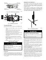
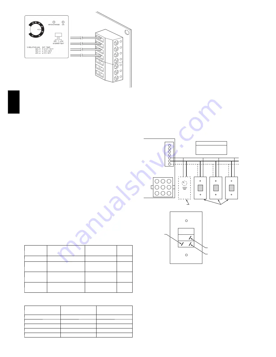
Push Button Timers may be used and are connected to the ERV as
shown in Figure 9. However, the Evolution system should be set to
continuous fan to ensure that the fresh air is circulated in the home.
In a Zoned System, at least one zone should be set to continuous
fan.
3
4
5
I
OC
OL
YELLOW
BLACK
RED
ELECTRONIC CONTROL
BOARD
BACK OF PUSH BUTTON SWITCH
J3
J1
6
7
8
9
4
1
7
5
2
8
6
3
9
BLACK Ð (J3-4)
COMMON
TERMINAL
STRIP
YELLOW Ð (J3-3)
INDICATOR
TERMINAL STRIP
RED Ð (J3-5)
SWITCH
TERMINAL STRIP
BLACK Ð
COMMON, (J3-4)
YELLOW Ð
INDICATOR, (J3-3)
THE WIRES FROM THE SWITCH
RED Ð
SWITCH, (J3-5)
(OC)
(I)
(OL)
(OPTIONAL)
60 MINUTE TIMER
(OPTIONAL)
PUSH BUTTON SWITCHES
(5 SWITCHES MAXIMUM)
A98386
Fig. 9 -- Push Button Timer Wiring Layout
OPERATING THE ERV WITH THE
EVOLUTION CONTROL
The ventilator has four settings in heating mode and three settings
in cooling mode.
Heating:
AUTO -- the ventilator selects the speed based on indoor
humidity and outdoor temperature. It may cycle on/off every
30 minutes depending on humidity and outside temperature.
LOW -- low speed all of the time.
HIGH -- high speed all of the time.
ER
V

