
6
NOTE
:
The unit is considered balanced even if there is a
difference of
±
10 CFM (or
±
5 l/s or 17 m
3
/h) between the two air
flows.
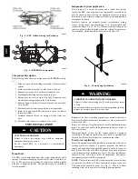
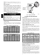
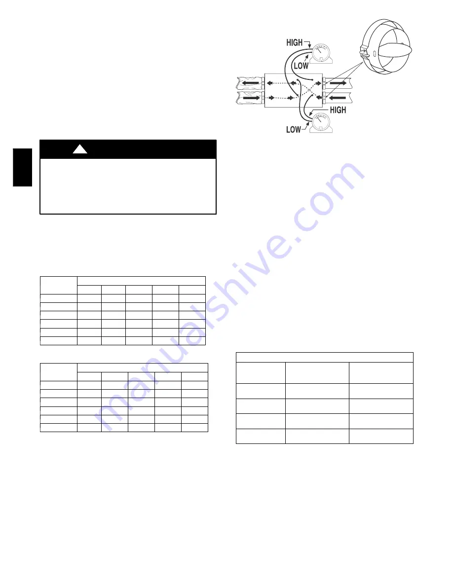
Balancing Dampers
Balancing dampers (sometimes called butterfly dampers) are
located in fresh--air intake and stale--air exhaust of the ERV. (See
Fig. 11.) Some field modification may be required to ensure proper
adjustment of balancing dampers while located in flexible duct.
Insulating over these dampers is strongly recommended after
balancing is complete to prevent condensation problems.
NOTE
: Temporary flow collars are not needed with the new
ERVBBHA models since the air flow pressure taps are
incorporated in the access door. (See Fig. 11.)
VENTILATION EVALUATION
UNIT DAMAGE HAZARD
Failure to follow this caution may result in reduced unit
efficiency, capacity or unit life.
DO NOT use ERV during construction of a house or when
sanding drywall. This type of dust may damage system.
CAUTION
!
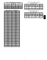
Ventilator Sizing
Tables 3 and 4 should be used to determine the required airflow for
a home. These guidelines are taken from ANSI/ASHRAE
62.2--2007.
Table 3 – Ventilation Air Requirements, cfm
FLOOR
AREA (ft
2
)
BEDROOMS
0---1
2---3
4---5
6---7
>7
<1500
30
45
60
75
90
1501---3000
45
60
75
90
105
3001---4500
60
75
90
105
120
4501---6000
75
90
105
120
135
6001---7500
90
105
120
135
150
>7500
105
120
135
150
165
Table 4 – Ventilation Air Requirements, L/s
FLOOR
AREA (m
2
)
BEDROOMS
0---1
2---3
4---5
6---7
>7
<139
14
21
28
35
42
139.1---279
21
28
35
42
50
279.1---418
28
35
42
50
57
418.1---557
35
42
50
57
64
557.1---697
42
50
57
64
71
>697
50
57
64
71
78
Fresh air flow
Exhaust Air Flow
A05264
Fig. 11 -- Balancing ERVBBHA
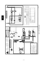
CONTROL BOARD OPERATION
Board Function
To ensure proper operation of ERV, configuration jumpers are
located on electronic control board and must match configuration
setup shown in Fig. 12 under Jumper Table. Jumpers are factory set
and do not require any changes unless control board is replaced. If
control board is replaced, or unusual start--up operation is
encountered, check jumpers to make sure they are located properly.
NOTE
: Power disconnect for 30 seconds is required to reset the
CPU when changing jumpers.
Outdoor Ambient Below 23
_
F (--5
_
C)
The ERV continually monitors outside air temperature. If outside
air is at or below 23
_
F (--5
_
C), ERV will cycle between air
exchange and defrost.
The ERV measure the incoming air temperature and will cycle unit
in and out of defrost, depending on outdoor ambient. The intake
damper will close and circulate indoor air through the core for 6 to
10 minutes. This time depends on jumper location. Refer to Table 5
for defrost cycle.
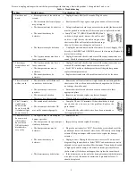
Table 5 – Defrost Cycle
ERV DEFROST CYCLES
Outside
Temp
°
F /
°
C
Standard
Defrost (as shipped)
Extended Defrost
(Jumper JU1---F
Removed)
Above 23
°
F /
---5
°
C
No Defrost
No Defrost
23 to 5
°
F /
---5 to ---15
°
C
10 Minute Defrost/60
Minute Exchange
10 Minute Defrost/30
Minute Exchange
4 to ---17
°
F /
---16 to ---27
°
C
10 Minute Defrost/30
Minute Exchange
10 Minute Defrost/20
Minute Exchange
Below ---18
°
F /
---28
°
C
10 Minute Defrost/20
Minute Exchange
10 Minute Defrost/15
Minute Exchange
OFF and INTERMITTENT/OFF Mode
When ERV is Off, K1 relay is open (see Fig. 12).
High--Speed Air Exchange
When high--speed air exchange occurs, K1 relay closes and K2 (12
VDC relay) is energized. This opens low--speed contacts, and
closes high--speed contacts. Then, 115 VAC is applied between
orange and gray wires on Molex
R
plug (pins 1 and 6) and blower
motor runs in high--speed operation. Also, 115 VAC is applied
across pins 5 and 7, this energizes interlock relay (see Fig. 12).
Low--Speed Air Exchange
When low--speed air exchange occurs, K1 relay closes and K2 (12
VDC relay) is de--energized. This keeps low--speed contacts closed
and high--speed contacts open. Then, 115 VAC is applied between
ER
V


