background image

8

NOTE

: If, after using the following test, you still hear relays

clicking upon charge, carefully check wiring, blower capacitor, and
blowers.
Alternate procedure to check blower speed:
Blower Speed Test
HIGH SPEED

1. Disconnect ERV from 115 VAC.
2. Unplug wall control wires at control module terminal block

inside ERV.

3. Plug ERV back to 115 VAC.
4. Attach a wire across J3--8 and J3--9 (B and G) on control

module terminal block.

5. Push in door switch, this will initiate a high--speed ex-

change.

LOW SPEED

1. Unplug ERV from 115 VAC.
2. Disconnect wall control wires at control module terminal

block inside ERV.

3. Plug ERV back to 115 VAC.
4. Connect a 3.0 K ohm resistor between B and G on control

module terminal block.

5. Push in door switch, this will initiate a low--speed exchange.

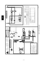
Blower Speed Selection

Three--speed blowers are factory connected to electronic control

board on HIGH-- and LOW--speed taps of blowers. Installer can
easily change low--speed tap to medium--speed tap so electronic

control will select between high and medium speed. Connections
can be changed at motor location (see Table 9 and 10).
To change low speed to medium speed, proceed as follows:

1. Unplug unit from 115 VAC.
2. Remove filters and core from ERV.
3. Slide blower assembly to the right until wire connections

are visible.

4. Locate red wire and blue wire coming from blower assem-

bly.

5. Unplug red wire from quick connect.
6. Unplug protecting cap quick connection from blue wire and

put on red wire coming from blower. The cap is a safety
insulator.

7. Connect red wire of main harness to blue wire.
8. Replace wires, blower assembly, filters, and core.

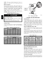
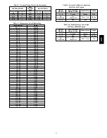
Outdoor Air Thermistor

When unit is not responding to wall control, check outdoor air
thermistor.

1. Remove thermistor wire from control board.
2. Take ohm reading across thermistor.
3. Refer to Table 8 for temperature/ohm relationship.

ER

V

Summary of Contents for ERVBBLHA Series

Page 1: ...CAUTION These words are used with the safety alert symbol DANGER identifies the most serious hazards which will result in severe personal injury or death WARNING signifies hazards which could result in personal injury or death CAUTION is used to identify unsafe practices which may result in minor personal injury or product and property damage NOTE is used to highlight suggestions which will result...

Page 2: ... air pickup registers throughout the home Fresh air registers are normally located in bedrooms dining rooms living rooms and basements It is recommended that registers be placed 6 to 12 152 to 305 mm from the ceiling on an interior wall and airflow directed toward the ceiling If registers are floor installed airflow should be directed toward the wall A92269 Fig 4 Chain Spring Installation CARBON M...

Page 3: ...g between ERV and exterior wall Fresh air intake and stale air exhaust must be separated by at least 6 ft 1 8 m Fresh air intake must be positioned at least 10 ft 3 m from nearest dryer vent furnace exhaust driveway gas meter or oil fill pipe Fresh air intake must be positioned as far as possible from garbage containers and potential chemical fumes When possible it is advised to locate the intake ...

Page 4: ...35 45 4 F 20 C 30 45 22 F 30 C 25 35 NOTE The ERV may be controlled using the Evolution system control The ERV may be connected using either a NIM or a 4 Zone Damper Module See the appropriate instructions if using the NIM of a 4 Zone Damper Module for connection instructions OneTouch Control The OneTouch control may be used as the primary wall control for the ERV This control will step through th...

Page 5: ...d optimum performance when applying an ERV Unit balancing prevents a positive and or negative pressure within the home Balancing the ERV is done by using balancing dampers in the fresh air intake and stale air exhaust ducts Airflow is determined by temporarily connecting a magnehelic gauge to the pressure taps on ERV See Fig 10 Balancing chart is located on unit door A98400 Fig 10 Magnehelic Gauge...

Page 6: ...h configuration setup shown in Fig 12 under Jumper Table Jumpers are factory set and do not require any changes unless control board is replaced If control board is replaced or unusual start up operation is encountered check jumpers to make sure they are located properly NOTE Power disconnect for 30 seconds is required to reset the CPU when changing jumpers Outdoor Ambient Below 23_ F 5_ C The ERV...

Page 7: ...n outdoor temperature is between 60 F and 75 F 16 C and 24 C and it is dry UNIT COMPONENT DAMAGE HAZARD Failure to follow this caution may result in equipment damage or improper operation DO NOT use water to clean core or damage will result In addition before servicing or removing the core inspect the edges to see if they appear soft or slightly expanded This can be normal and due to moisture in t...

Page 8: ...ory connected to electronic control board on HIGH and LOW speed taps of blowers Installer can easily change low speed tap to medium speed tap so electronic control will select between high and medium speed Connections can be changed at motor location see Table 9 and 10 To change low speed to medium speed proceed as follows 1 Unplug unit from 115 VAC 2 Remove filters and core from ERV 3 Slide blowe...

Page 9: ...l may be defective S Remove the wall control and test it right beside the unit using another shorter wire If the wall control works there change the wire If it does not change the wall control S The wires may be in reverse position S Ensure that the color coded wires have been connected to their appropriate places S The wires may be broken S Inspect every wire and replace any that are damaged S Th...

Page 10: ...er Le non respect de ces instructions peut causer un décès ou un choc électrique ADVERTENCIA PELIGRO DE CHOQUE ELÉCTRICO Desconecte el suministro de energía antes de reparar de mantener o de cablear in situ Vuelva a colocar todos los paneles antes de hacer lo funcionar No seguir estas instrucciones puede causar la muerte o choque eléctrico NOTES 1 CONTROLS AVAILABLE SEE THE INSTRUCTION MANUAL 2 IF...

Page 11: ... 11 860 72 22 11 270 74 23 10 750 76 24 10 250 78 26 9 750 80 27 9 300 82 28 8 840 84 29 8 432 86 30 8 042 88 31 7 668 90 32 7 310 92 33 6 993 94 34 6 661 96 36 6 368 98 37 6 085 100 38 5 811 102 39 5 571 104 40 5 313 106 41 5 088 108 42 4 869 110 43 4 660 112 44 4 450 114 46 4 268 116 47 4 019 118 48 3 918 120 49 3 750 Table 9 Factory Set Blower Connection HIGH or LOW Speed Control Module Main El...

Page 12: ... change at any time specifications or designs without notice and without incurring obligations E2009 Bryant Heating Cooling Systems 7310 W Morris St Indianapolis IN 46231 Printed in U S A Edition Date 03 09 Replaces IIERVLHA 01 Catalog No IIERVLHA 02 ERV ...

Reviews: