8
Connect Ground and Power Wires
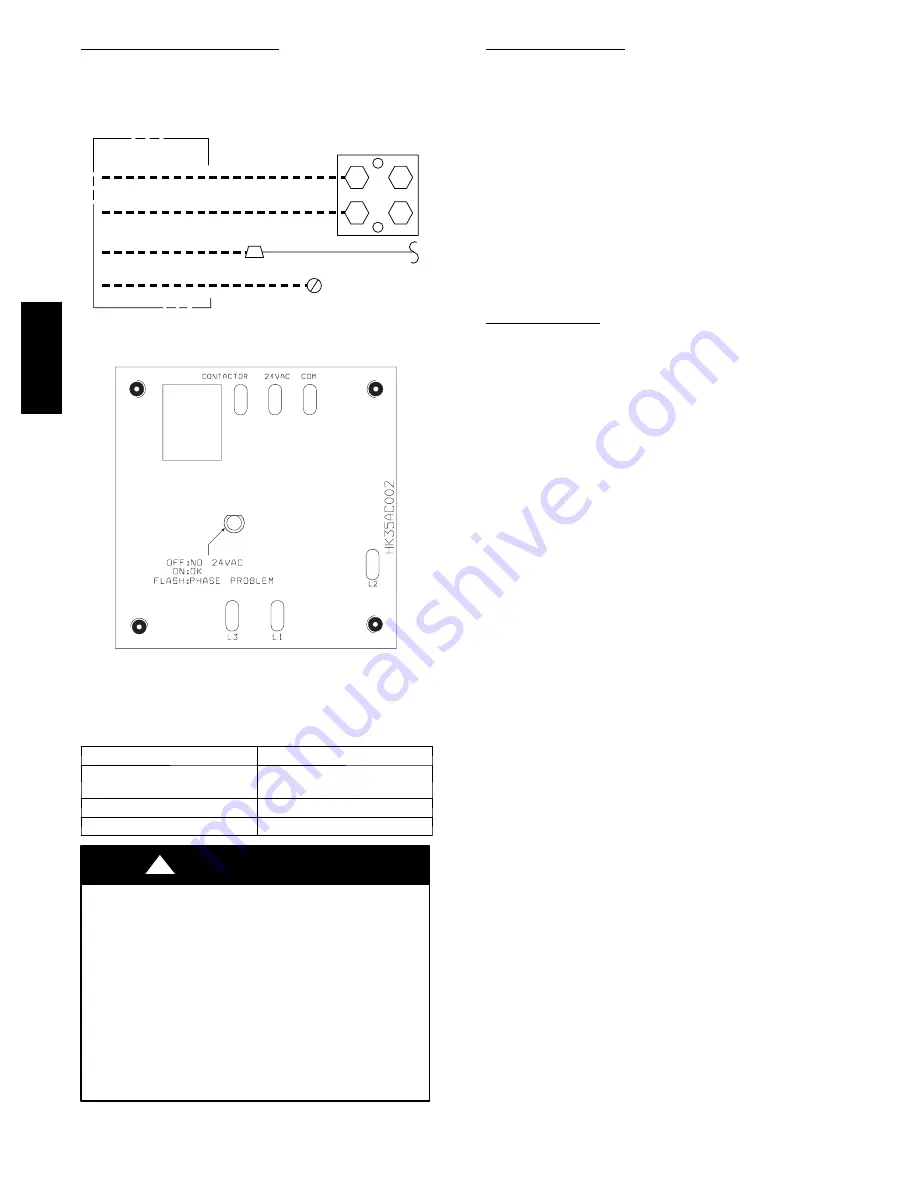
Connect ground wire to ground connection in control box for
safety. Connect power wiring to contactor as shown in Fig. 8.
DISCONNECT
PER N.E.C. AND/OR
LOCAL CODES
CONTACTOR
GROUND
LUG
FIELD GROUND
WIRING
FIELD POWER
WIRING
BLUE
3 PHASE ONLY
A94025
Fig. 8
---
Line Connections
A00010
Fig. 9
---
3--Phase Monitor Control
(Applies to 3--Phase Units Only)
Table 3—Phase Monitor LED Indicators
LED
STATUS
OFF
No call for compressor opera-
tion
FLASHING
Reversed phase
ON
Normal
UNIT DAMAGE HAZARD
Failure to follow this caution may result in equipment
damage or improper operation.
Ensure compressor rotation is correct.
S
3--phase scroll compressors are rotation
sensitive.
S
A flash LED on phase monitor indicates
reverse rotation. (See Fig. 9 and Table 3)
This will not allow contractor to be energized.
S
Disconnect power to unit and interchange 2
field--wiring leads on unit contactor.
CAUTION
!
Connect Control Wiring
Route 24--v control wires through control wiring grommet and
connect leads to control wiring. Refer to Installation Instruction
packaged with thermostat.
Use No. 18 AWG color--coded, insulated (35
_
C minimum) wire.
If thermostat is located more than 100 ft. from unit, as measured
along the control voltage wires, use No. 16 AWG color--coded
wire to avoid excessive voltage drop.
All wiring must be NEC Class 1 and must be separated from
incoming power leads.
Use furnace transformer, fan coil transformer, or accessory
transformer for control power, 24--v/40--va minimum.
NOTE
: Use of available 24--v accessories may exceed the
minimum 40--va power requirement. Determine total transformer
loading and increase the transformer capacity or split the load
with an accessory transformer as required.
Final Wiring Check
IMPORTANT
: Check factory wiring and field wire connections
to ensure terminations are secured properly. Check wire routing
to ensure wires are not in contact with tubing, sheet metal, etc.
STEP 8
—
Compressor Crankcase Heater
When equipped with a crankcase heater, furnish power to heater a
minimum of 24 hr before starting unit. To furnish power to heater
only, set thermostat to OFF and close electrical disconnect to
outdoor unit.
A crankcase heater is required if refrigerant tubing is longer than
80 ft. Refer to the Longline Guideline Section -- Residential
Split--System Air Conditioners and Heat Pumps Using Puron
Refrigerant.
STEP 9
—
Install Electrical Accessories
Refer to the individual instructions packaged with kits or
accessories when installing.
123A
/124A


