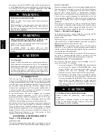
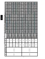
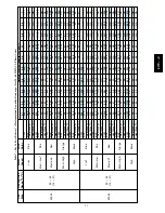
10
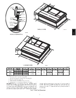
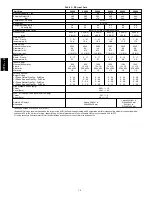
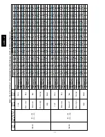
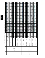
Table 1 – Physical Data
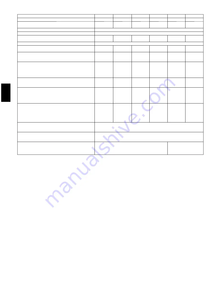
Unit Size
24040
24060
30040
30060
36060
36090
Nominal Capacity --- ton
2
2
2.5
2.5
3
3
Shipping Weight (lb)
(kg)
365
166
365
166
395
179
395
179
440
200
440
200
Compressor / Quantity
Scroll / 1
Refrigerant
R---410A
Refrigerant Quantity (lb)
Quantity (kg)
7.5
3.4
7.5
3.4
9.0
4.1
9.0
4.1
8.9
4.0
8.9
4.0
Refrigerant Metering Device
Indoor TXV, Outdoor Dual Accuraters
Orifice OD (in)
(mm)
0.032 (2)
0.81 (2)
0.032 (2)
0.81 (2)
0.035 (2)
0.89 (2)
0.035 (2)
0.89 (2)
0.040 (2)
1.02 (2)
0.040 (2)
1.02 (2)
Outdoor Coil
Rows
…
Fins/in,
face area (sq. ft.)
1
…
21
15.4
1
…
21
15.4
1
…
21
18.8
1
…
21
18.8
1
…
21
17.5
1
…
21
17.5
Outdoor Fan
Nominal Airflow (cfm)
Diameter (in.)
Diameter (mm)
Motor hp (rpm)
2500
24
610
1/12 (810)
2500
24
610
1/12 (810)
3000
24
610
1/10 (810)
3000
24
610
1/10 (810)
3500
26
660
1/5 (810)
3500
26
660
1/5 (810)
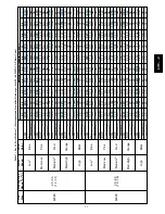
Indoor Coil
Rows
…
Fins/in,
face area (sq. ft.)
3
…
17
3.7
3
…
17
3.7
3
…
17
3.7
3
…
17
3.7
2
…
15
5.6
2
…
17
5.6
Indoor Blower
Nominal Airflow (cfm)
Size (in.)
Size (mm)
Motor hp
800
10 x 10
254 x 254
1/2
800
10 x 10
254 x 254
1/2
1000
10 x 10
254 x 254
1/2
1000
10 x 10
254 x 254
1/2
1200
11 x 10
279 x 254
1/2
1200
11 x 10
279 x 254
1/2
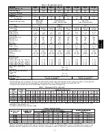
Furnace Section*
Burner Orifice
1---Phase Natural Gas Qty
…
Drill Size
1---Phase Propane Gas Qty
…
Drill Size
3---Phase Natural Gas Qty
…
Drill Size
3---Phase Propane Gas Qty
…
Drill Size
2
…
44
2
…
55
2
…
44
2
…
55
3
…
44
3
…
55
2
…38
2…53
2
…
44
2
…
55
2
…
44
2
…
55
3
…
44
3
…
55
2
…38
2…53
3
…
44
3
…
55
2
…38
2…53
3
…
38
3
…
53
3
…
38
3
…
53
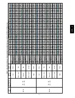
High Pressure Switch (psig)
Cutout
Reset (Auto)
650 +/--- 15
420 +/--- 25
Loss---of---Charge/Low Pressure Switch (psig)
Cutout
Reset (Auto)
20 +/--- 5
45 +/--- 10
Return Air Filters
{}
disposable
2 each 20x12x1 in.
508x305x25 mm
1 each 24x16x1 in.
610x406x25 mm
24x18x1 in.
510x457x25 mm
*Based on altitude of 0 to 2000 ft (0---610 m).
{
Required filter sizes shown are based on the larger of the AHRI (Air Conditioning Heating and Refrigeration Institute) rated cooling airflow or the heating airflow
velocity of 300 to 350 ft/minute for high---capacity type. Air filter pressure drop for non---standard filters must not exceed 0.08 IN. W.C.
}
If using accessory filter rack refer to filter rack installation instructions for correct filter size and quantity.
677C
--
--
C
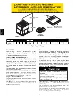
Summary of Contents for Legacy 677C**C Series
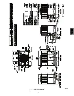
Page 3: ...3 A150538 Fig 2 24 30 Unit Dimensions 677C C...
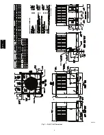
Page 4: ...4 A150539 Fig 3 36 60 Unit Dimensions 677C C...
Page 44: ...44 A150506 Fig 15 208 230 1 60 Connection Wiring Diagram 677C C...
Page 45: ...45 A150516 Fig 15 Cont 208 230 1 60 Ladder Wiring Diagram 677C C...
Page 46: ...46 A150507 Fig 16 208 230 3 60 Connection Wiring Diagram 677C C...
Page 47: ...47 A150517 Fig 16 Cont 208 230 3 60 Ladder Wiring Diagram 677C C...