
11
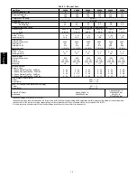
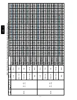
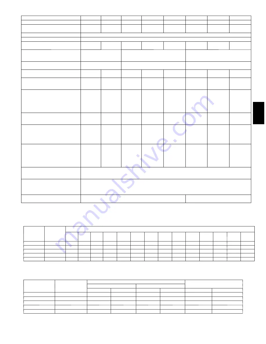
Table 1 -- Physical Data Cont’d)
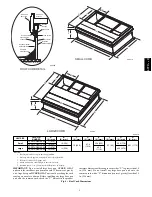
Unit Size
42060
42090
48090
48115
48130
60090
60115
60130
Nominal Capacity --- ton
3.5
3.5
4
4
4
5
5
5
Shipping Weight (lb)
(kg)
475
215
475
215
500
227
500
227
500
227
515
234
515
234
515
234
Compressor / Quantity
Scroll / 1
Refrigerant
R---410A
Refrigerant Quantity (lb)
Quantity (kg)
11.2
5.1
11.2
5.1
9.9
4.5
9.9
4.5
9.9
4.5
11.9
5.4
11.9
5.4
11.9
5.4
Refrigerant Metering Device
Indoor TXV,
Outdoor Dual
Accuraters
Indoor Accurater,
Outdoor Dual Accuraters
Indoor TXV,
Outdoor Dual Accuraters
Orifice ID (in)
(mm)
N/A
0.080 (1)
2.03 (1)
N/A
Orifice OD (in)
(mm)
0.046 (2)
1.17 (2)
0.046 (2)
1.17 (2)
0.046 (2)
1.17 (2)
0.046 (2)
1.17 (2)
0.046 (2)
1.17 (2)
0.052 (2)
1.32 (2)
0.052 (2)
1.32 (2)
0.052 (2)
1.32 (2)
Outdoor Coil
Rows
…
Fins/in,
face area (sq. ft.)
1
…
21
23.3
1
…
21
23.3
1
…
21
23.3
1
…
21
23.3
1
…
21
23.3
2
…
21
17.5
2
…
21
17.5
2
…
21
17.5
Outdoor Fan
Nominal Airflow (cfm)
Diameter (in.)
Diameter (mm)
Motor hp
Motor (rpm)
3500
26
660
1/5
(810)
3500
26
660
1/5
(810)
3500
26
660
1/5
(810)
3500
26
660
1/5
(810)
3500
26
660
1/5
(810)
3500
26
660
1/4
(810)
3500
26
660
1/4
(810)
3500
26
660
1/4
(810)
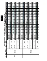
Indoor Coil
Rows
…
Fins/in,
face area (sq. ft.)
3
…
17
4.7
3
…
17
4.7
3
…
17
4.7
3
…
17
4.7
3
…
17
4.7
3
…
17
5.6
3
…
17
5.6
3
…
17
5.6
Indoor Blower
Nominal Airflow (cfm)
Size (in.)
Size (mm)
Motor hp
1350
11 x 10
279 x 254
1/2
1350
11 x 10
279 x 254
1/2
1600
11 x 10
279 x 254
1
1600
11 x 10
279 x 254
1
1600
11 x 10
279 x 254
1
1750
11 x 10
279 x 254
1
1750
11 x 10
279 x 254
1
1750
11 x 10
279 x 254
1
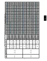
Furnace Section*
Burner Orifice
1 Phase Natural Gas Qty
…
Drill Size
1 Phase Propane Gas Qty
…
Drill Size
3 Phase Natural Gas Qty
…
Drill Size
3 Phase Propane Gas Qty
…
Drill Size
3
…
44
3
…
55
2
…38
2…53
3
…
38
3
…
53
3
…
38
3
…
53
3
…
38
3
…
53
3
…
38
3
…
53
3
…
33
3
…
51
3
…
33
3
…
51
3
…
31
3
…
49
3
…
31
3
…
49
3
…
38
3
…
53
3
…
38
3
…
53
3
…
33
3
…
51
3
…
33
3
…
51
3
…
31
3
…
49
3
…
31
3
…
49
High Pressure Switch (psig)
Cutout
Reset (Auto)
650 +/--- 15
420 +/--- 25
Loss---of---Charge/Low Pressure
Switch (psig)
Cutout
Reset (Auto)
20 +/--- 5
45 +/--- 10
Return Air Filters
{}
disposable
1 each 24x14x1 (610x356x25)
24x15x1 (610x406x25)
1 each 24x16x1 (610x406x25)
24x18x1 (610x457x25)
*Based on altitude of 0 to 2000 ft (0---610 m).
{
Required filter sizes shown are based on the larger of the AHRI (Air Conditioning Heating and Refrigeration Institute) rated cooling airflow or the heating airflow
velocity of 300 to350 ft/minute for high---capacity type. Air filter pressure drop for non---standard filters must not exceed 0.08 IN. W.C.
}
If using accessory filter rack refer to filter rack installation instructions for correct filter size and quantity.
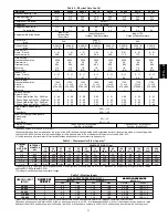
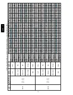
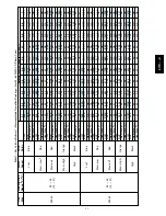
Table 2 – Maximum Gas Flow Capacity*
NOMINAL
IRON
PIPE, SIZE
(IN.)
INTERNAL
DIAMETER
(IN.)
LENGTH OF PIPE, FT (m)†
10
(3.0)
20
(6.1)
30
(9.1)
40
(12.2)
50
(15.2)
60
(18.3)
70
(21.3)
80
(24.4)
90
(27.4)
100
(30.5)
125
(31.1)
150
(45.7)
175
(53.3)
200
(61.0)
1/2
.622
175
120
97
82
73
66
61
57
53
50
44
40
—
—
3/4
.824
360
250
200
170
151
138
125
118
110
103
93
84
77
72
1
1.049
680
465
375
320
285
260
240
220
205
195
175
160
145
135
1---1/4
1.380
1400
950
770
600
580
530
490
460
430
400
360
325
300
280
1---1/2
1.610
2100
1460
1180
990
900
810
750
690
650
620
550
500
460
430
* Capacity of pipe in cu ft of gas per hr for gas pressure of 0.5 psig or less. Pressure drop of 0.5--IN. W.C. (based on a 0.60 specific gravity gas). Refer to Table 2
and the NFGC NFPA 54/ANSI Z 223.1.
† This length includes an ordinary number of fittings.
Table 3 – Heating Inputs
HEATING INPUT
(BTUH)
NUMBER OF
GAS SUPPLY PRESSURE (IN. W.C.)
MANIFOLD PRESSURE
NUMBER OF
ORIFICES
Natural
{
Propane*
{
MANIFOLD PRESSURE
(IN. W.C.)
ORIFICES
Min
Max
Min
Max
Natural
{
Propane*†
40,000
2
4.0
13.0
11.0
13.0
3.2
3.8
10.0
60,000
3
4.0
13.0
11.0
13.0
3.2
3.8
10.0
90,000
3
4.5
13.0
11.0
13.0
3.2
3.8
10.0
115,000
3
4.5
13.0
11.0
13.0
3.2
3.8
10.0
130,000
3
4.5
13.0
11.0
13.0
3.2
3.8
10.0
*
When a unit is converted to propane, different size orifices must be used. See separate, natural---to---propane conversion kit instructions.
{
Based on altitudes from sea level to 2000 ft (610 m) above sea level. In th e U.S.A. for altitudes above 2000 ft (610 m), reduce input rating 4 percent for each
additional 1000 ft (305 m) above sea level. In Canada, from 2000 ft (610 m) above sea level to 4500 ft (1372 m) above sea level, derate the unit 10 percent.
677C
--
--
C
Summary of Contents for Legacy 677C**C Series
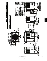
Page 3: ...3 A150538 Fig 2 24 30 Unit Dimensions 677C C...
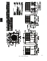
Page 4: ...4 A150539 Fig 3 36 60 Unit Dimensions 677C C...
Page 44: ...44 A150506 Fig 15 208 230 1 60 Connection Wiring Diagram 677C C...
Page 45: ...45 A150516 Fig 15 Cont 208 230 1 60 Ladder Wiring Diagram 677C C...
Page 46: ...46 A150507 Fig 16 208 230 3 60 Connection Wiring Diagram 677C C...
Page 47: ...47 A150517 Fig 16 Cont 208 230 3 60 Ladder Wiring Diagram 677C C...


