
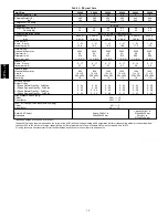
12
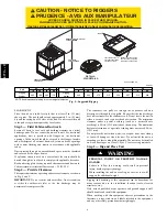
Step 10 — Install Electrical Connections
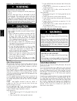
ELECTRICAL SHOCK HAZARD
Failure to follow this warning could result in personal injury
or death.
The unit cabinet must have an uninterrupted, unbroken
electrical ground. This ground may consist of an electrical
wire connected to the unit ground screw in the control
compartment, or conduit approved for electrical ground when
installed in accordance with NEC, NFPA 70 National Fire
Protection Association (latest edition) (in Canada, Canadian
Electrical Code CSA C22.1) and local electrical codes.
!
WARNING
UNIT COMPONENT DAMAGE HAZARD
Failure to follow this caution may result in damage to the unit
being installed.
1. Make all electrical connections in accordance with NEC
NFPA 70 (latest edition) and local electrical codes
governing such wiring. In Canada, all electrical
connections must be in accordance with CSA standard
C22.1 Canadian Electrical Code Part 1 and applicable
local codes. Refer to unit wiring diagram.
2. Use only copper conductor for connections between
field--supplied electrical disconnect switch and unit. DO
NOT USE ALUMINUM WIRE.
3. Be sure that high--voltage power to unit is within
operating voltage range indicated on unit rating plate. On
3--phase units, ensure phases are balanced within 2
percent. Consult local power company for correction of
improper voltage and/or phase imbalance.
4. Insulate low--voltage wires for highest voltage contained
within conduit when low--voltage control wires are in
same conduit as high--voltage wires.
5. Do not damage internal components when drilling
through any panel to mount electrical hardware, conduit,
etc.
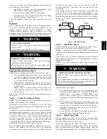
!
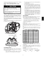
CAUTION
High--Voltage Connections
When routing power leads into unit, use only copper wire between
disconnect and unit. The high voltage leads should be in a conduit
until they enter the duct panel; conduit termination at the duct
panel must be watertight.
The unit must have a separate electrical service with a
field--supplied, waterproof disconnect switch mounted at, or within
sight from, the unit. Refer to the unit rating plate, NEC and local
codes for maximum fuse/circuit breaker size and minimum circuit
amps (ampacity) for wire sizing.
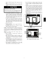
The field--supplied disconnect switch box may be mounted on the
unit over the high--voltage inlet hole when the standard power and
low--voltage entry points are used (See Fig. 2 and 3 for acceptable
location).
NOTE
:
Field supplied disconnect switch box should be
positioned so that it does not cover up any of the unit gas
combustion supply air louvers.
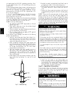
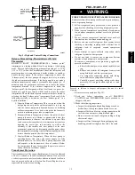
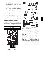
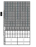
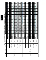
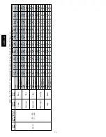
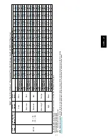
See unit wiring label (Fig. 15 and 16) and Fig. 9 for reference
when making high voltage connections. Proceed as follows to
complete the high--voltage connections to the unit.
Single phase units:
1. Run the high--voltage (L1, L2) and ground lead into the
control box.
2. Connect ground lead to chassis ground connection.
3. Locate the black and yellow wires connected to the line side
of the contactor.
4. Connect field L1 to black wire on connection 11 of the
compressor contactor.
5. Connect field wire L2 to yellow wire on connection 23 of
the compressor contactor.
Three--phase units:
1. Run the high--voltage (L1, L2, L3) and ground lead into the
control box.
2. Connect ground lead to chassis ground connection.
3. Locate the black and yellow wires connected to the line side
of the contactor.
4. Connect field L1 to black wire on connection 11 of the
compressor contactor.
5. Connect field wire L3 to yellow wire on connection 13 of
the compressor contactor.
6. Connect field wire L2 to blue wire from compressor.
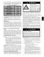
Special Procedures for 208--V Operation
ELECTRICAL SHOCK HAZARD
Failure to follow this warning could result in personal injury
or death.
Make sure the power supply to the unit is switched OFF before
making any wiring changes. Tag the disconnect switch with a
suitable warning label. With disconnect switch open, move
black wire from transformer (3/16 in.) terminal marked 230 to
terminal marked 200. This retaps transformer to primary
voltage of 208 vac.
!
WARNING
ELECTRICAL SHOCK HAZARD
Failure to follow this warning could result in personal injury
or death.
Before making any wiring changes,
make sure
the gas supply
is switched off first.
Then
switch off the power supply to the
unit and install lockout tag.
!
WARNING
Control Voltage Connections
Do not use any type of power--stealing thermostat. Unit control
problems may result.
Use no. 18 American Wire Gage (AWG) color--coded, insulated
(35
_
C minimum) wires to make the control voltage connections
between the thermostat and the unit. If the thermostat is located
more than 100 ft (30.5 m) from the unit (as measured along the
control voltage wires), use no. 16 AWG color--coded, insulated
(35
_
C minimum) wires.
Locate the seven (eight on 3--phase) low voltage thermostat leads
in 24 volt splice box. See Fig. 9 for connection diagram. Run the
low--voltage leads from the thermostat, through the control wiring
inlet hole grommet (Fig. 2 and 3), and into the low--voltage splice
box. Provide a drip loop before running wires through panel.
Secure and strain relief all wires so that they do not interfere with
operation of unit. A gray wire is standard on 3--phase unit for
connection to an economizer.
677C
--
--
C
Summary of Contents for Legacy 677C**C Series
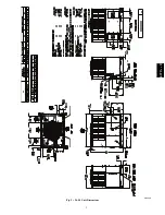
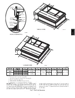
Page 3: ...3 A150538 Fig 2 24 30 Unit Dimensions 677C C...
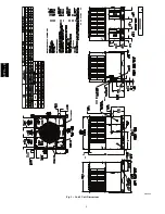
Page 4: ...4 A150539 Fig 3 36 60 Unit Dimensions 677C C...
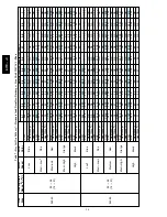
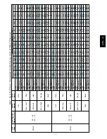
Page 44: ...44 A150506 Fig 15 208 230 1 60 Connection Wiring Diagram 677C C...
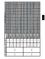
Page 45: ...45 A150516 Fig 15 Cont 208 230 1 60 Ladder Wiring Diagram 677C C...
Page 46: ...46 A150507 Fig 16 208 230 3 60 Connection Wiring Diagram 677C C...
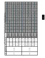
Page 47: ...47 A150517 Fig 16 Cont 208 230 3 60 Ladder Wiring Diagram 677C C...


