
16
When the gas supply being used has a different heating value or
specific gravity, refer to national and local codes, or contact your
distributor to determine the required orifice size.
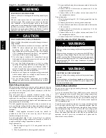
UNIT DAMAGE HAZARD
Failure to follow this caution may result in reduced unit
and/or component life.
Do Not
redrill an orifice. Improper drilling (burrs,
out--of--round holes, etc.) can cause excessive burner noise
and misdirection of burner flame. If orifice hole appears
damaged or it is suspected to have been redrilled, check
orifice hole with a numbered drill bit of correct size.
!
CAUTION
Adjust Gas Input
The gas input to the unit is determined by measuring the gas flow
at the meter or by measuring the manifold pressure. Measuring the
gas flow at the meter is recommended for natural gas units. The
manifold pressure must be measured to determine the input of
propane gas units.
Measure Gas Flow (Natural Gas Units)
Minor adjustment to the gas flow can be made by changing the
manifold pressure. The manifold pressure must be maintained
between 3.2 and 3.8 IN. W.C.
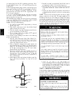
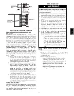
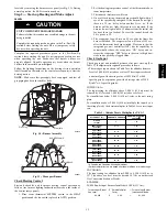
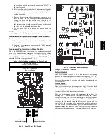
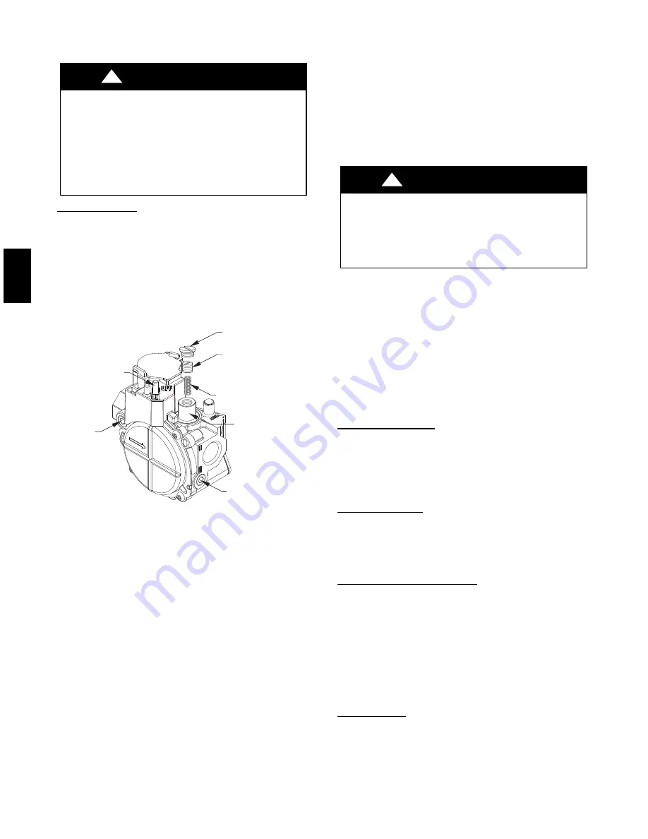
REGULATOR
COVER SCREW
ADJUSTMENT
SCREW
REGULATOR SPRING
(PROPANE - WHITE)
NATURAL - SILVER)
GAS PRESSURE
REGULATOR
ADJUSTMENT
MANIFOLD
PRESSURE TAP
INLET
PRESSURE TAP
ON/OFF SWITCH
PLASTIC
(
A07751
Fig. 12 -- Single--Stage Gas Valve
If larger adjustments are required, change main burner orifices
following the recommendations of national and local codes.
NOTE
:
All other appliances that use the same meter must be
turned off when gas flow is measured at the meter.
Proceed as follows:
1. Turn off gas supply to unit.
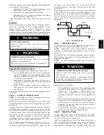
2. Remove pipe plug on manifold (See Fig. 10) and connect
manometer. Turn on gas supply to unit.
3. Record number of seconds for gas meter test dial to make
one revolution.
4. Divide number of seconds in Step 3 into 3600 (number of
seconds in one hr).
5. Multiply result of Step 4 by the number of cubic feet (cu ft)
shown for one revolution of test dial to obtain cubic feet (cu
ft) of gas flow per hour.
6. Multiply result of Step 5 by Btu heating value of gas to
obtain total measured input in Btuh. Compare this value
with heating input shown in Table 3 (Consult the local gas
supplier if the heating value of gas is not known).
EXAMPLE: Assume that the size of test dial is 1 cu ft, one
revolution takes 32 sec, and the heating value of the gas is 1050
Btu/ft
3
. Proceed as follows:
1. 32 sec. to complete one revolution.
2. 3600
32 = 112.5.
3. 112.5 x 1 =112.5 ft
3
of gas flow/hr.
4. 112.5 x 1050 = 118,125 Btuh input.
If the desired gas input is 115,000 Btuh, only a minor change in the
manifold pressure is required.
Observe manifold pressure and proceed as follows to adjust gas
input:
1. Remove regulator cover screw over plastic adjustment
screw on gas valve (See Fig. 12).
2. Turn plastic adjustment screw clockwise to increase gas
input, or turn plastic adjustment screw counterclockwise to
decrease input (See Fig. 12). Manifold pressure must be
between 3.2 and 3.8 IN. W.C.
FIRE AND UNIT DAMAGE HAZARD
Failure to follow this warning could result in personal
injury or death and/or property damage.
Unsafe operation of the unit may result if manifold pressure
is outside this range.
!
WARNING
3. Replace regulator cover screw on gas valve (See Fig. 12).
4. Turn off gas supply to unit. Remove manometer from
pressure tap and replace pipe plug on gas valve. (See Fig.
10.) Turn on gas to unit and check for leaks.
Measure Manifold Pressure (Propane Units)
Refer to propane kit installation instructions for properly checking
gas input.
NOTE
: For installations below 2,000 ft (610 m), refer to the unit
rating plate for proper propane conversion kit. For installations
above 2,000 ft (610 m), contact your distributor for proper propane
conversion kit.
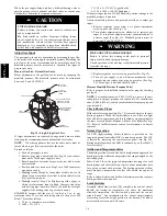
Check Burner Flame
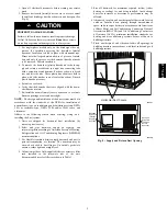
With control access panel (see Fig. 19) removed, observe the unit
heating operation. Watch the burner flames to see if they are light
blue and soft in appearance, and that the flames are approximately
the same for each burner. Propane will have blue flame (See Fig.
12). Refer to the Maintenance section for information on burner
removal.
Normal Operation
An LED (light--emitting diode) indicator is provided on the
integrated gas unit controller (IGC) to monitor operation. The IGC
is located by removing the control access panel (see Fig. 19).
During normal operation, the LED is continuously on (See Table 5
for error codes).
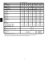
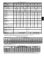
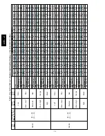
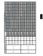
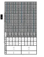
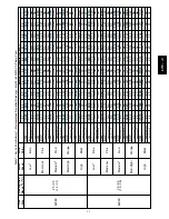
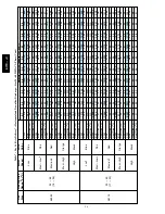
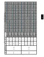
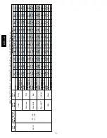
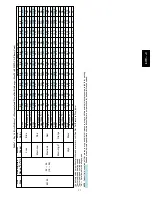
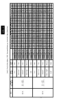
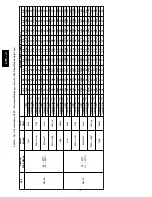
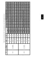
Airflow and Temperature Rise
The heating section for each size unit is designed and approved for
heating operation within the temperature--rise range stamped on the
unit rating plate.
Table 8 and 9 show the approved temperature rise range for each
heating input, and the air delivery cfm at various temperature rises
for a given external static pressure. The heating operation airflow
must produce a temperature rise that falls within the approved
range.
Refer to Indoor Airflow and Airflow Adjustments section to adjust
heating airflow when required.
Limit Switches
Normally closed limit switch (LS) completes the control circuit.
Should the leaving--air temperature rise above the maximum
allowable temperature, the limit switch opens and the control
circuit “breaks.” Any interruption in the control circuit instantly
closes the gas valve and stops gas flow to the burners. The blower
motor continues to run until LS resets.
677C
--
--
C
Summary of Contents for Legacy 677C**C Series
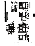
Page 3: ...3 A150538 Fig 2 24 30 Unit Dimensions 677C C...
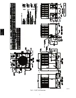
Page 4: ...4 A150539 Fig 3 36 60 Unit Dimensions 677C C...
Page 44: ...44 A150506 Fig 15 208 230 1 60 Connection Wiring Diagram 677C C...
Page 45: ...45 A150516 Fig 15 Cont 208 230 1 60 Ladder Wiring Diagram 677C C...
Page 46: ...46 A150507 Fig 16 208 230 3 60 Connection Wiring Diagram 677C C...
Page 47: ...47 A150517 Fig 16 Cont 208 230 3 60 Ladder Wiring Diagram 677C C...


