

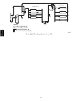
56
temperature. Normal temperature range is closed at 32
_
3
_
F (0
1.7
_
C) and open at 65
_
5
_
F (18
2.8
_
C).
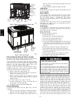
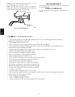
NOTE
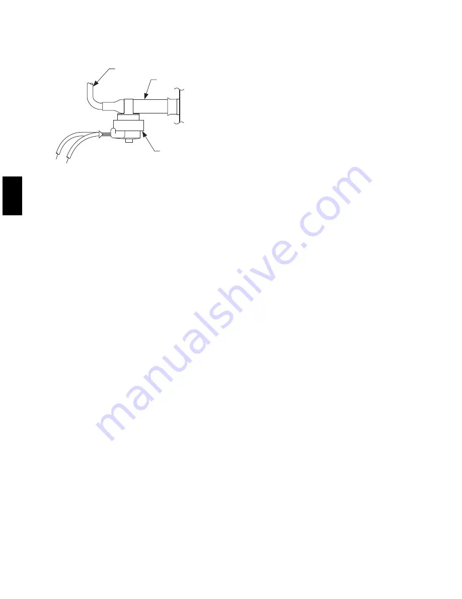
: The defrost thermostat must be located on the liquid side
of the outdoor coil on the bottom circuit and as close to the coil as
possible. The factor location is on the left/back coil.
FEEDER TUBE
STUB TUBE
DEFROST
THERMOSTAT
C99029
Fig. 28 -- Defrost Thermostat
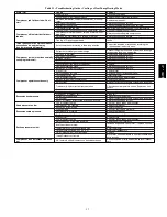
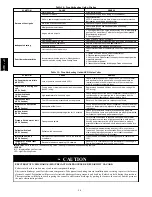
TROUBLESHOOTING
Use the Troubleshooting Guides (See Tables 13--15) if problems
occur with these units.
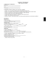
START--UP CHECKLIST
Use Start--Up checklist to ensure proper start--up procedures are
followed.
PURON
R
(R--410A) QUICK REFERENCE GUIDE
S
Puron refrigerant operates at 50--70 percent higher pressures than R--22. Be sure that servicing equipment and replacement
components are designed to operate with Puron
S
Puron refrigerant cylinders are rose colored.
S
Recovery cylinder service pressure rating must be 400 psig, DOT 4BA400 or DOT BW400.
S
Puron systems should be charged with liquid refrigerant. Use a commercial type metering device in the manifold hose when
charging into suction line with compressor operating
S
Manifold sets should be minimum 700 psig high side and 180 psig low side with 550 psig low--side retard.
S
Use hoses with minimum 700 psig service pressure rating.
S
Leak detectors should be designed to detect HFC refrigerant.
S
Puron, as with other HFCs, is only compatible with POE oils.
S
Vacuum pumps will not remove moisture from oil.
S
Do not use liquid--line filter driers with rated working pressures less than 600 psig.
S
Do not leave Puron suction line filter driers in line longer than 72 hrs.
S
Do not install a suction--line filter drier in liquid line.
S
POE oils absorb moisture rapidly. Do not expose oil to atmosphere.
S
POE oils may cause damage to certain plastics and roofing materials.
S
Wrap all filter driers and service valves with wet cloth when brazing.
S
A factory approved liquid--line filter drier is required on every unit.
S
Do NOT use an R--22 TXV.
S
Never open system to atmosphere while it is under a vacuum.
S
When system must be opened for service, recover refrigerant, evacuate then break vacuum with dry nitrogen and replace filter
driers. Evacuate to 500 microns prior to recharging.
S
Do not vent Puron into the atmosphere.
S
Observe all
warnings
,
cautions
, and
bold
text.
S
All indoor coils must be installed with a hard shutoff Puron TXV metering device.
677C
--
--
C
Summary of Contents for Legacy 677C**C Series
Page 3: ...3 A150538 Fig 2 24 30 Unit Dimensions 677C C...
Page 4: ...4 A150539 Fig 3 36 60 Unit Dimensions 677C C...
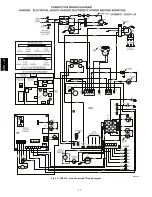
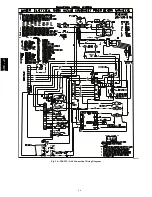
Page 44: ...44 A150506 Fig 15 208 230 1 60 Connection Wiring Diagram 677C C...
Page 45: ...45 A150516 Fig 15 Cont 208 230 1 60 Ladder Wiring Diagram 677C C...
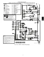
Page 46: ...46 A150507 Fig 16 208 230 3 60 Connection Wiring Diagram 677C C...
Page 47: ...47 A150517 Fig 16 Cont 208 230 3 60 Ladder Wiring Diagram 677C C...


