

58
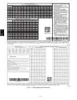
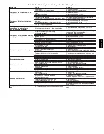
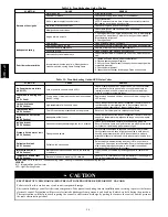
Table 14 – Troubleshooting Guide–Heating
SYMPTOM
CAUSE
REMEDY
Burners will not ignite
Water in gas line
Drain. Install drip leg.
No power to furnace
Check power supply fuses, wiring or circuit breaker.
No 24--v power supply to control circuit
Check transformer.
NOTE: Some transformers have internal over--current protection
that requires a cool--down period to reset.
Mis--wired or loose connections
Check all wiring and wire nut connections
Misaligned spark electrodes
Check flame ignition and sense electrode positioning.
Adjust as necessary.
No gas at main burners
1. Check gas line for air. Purge as necessary. NOTE: After purging
gas line of air, wait at least 5 minutes for any gas to dissipate be-
fore attempting to light unit.
2. Check gas valve.
Inadequate heating
Dirty air filter
Clean or replace filter as necessary
Gas input to furnace too low
Check gas pressure at manifold match with that on unit nameplate
Unit undersized for application
Replace with proper unit or add additional unit
Restricted airflow
Clean or replace filter. Remove any restriction.
Limit switch cycles main burners
Check rotation of blower, temperature rise of unit. Adjust as neces-
sary.
Poor flame characteristics
Incomplete combustion results in: Aldehyde odors,
carbon monoxide, sooting flame, floating flame
1. Tighten all screws around burner compartment
2. Cracked heat exchanger. Replace.
3. Unit over--fired. Reduce input (change orifices or adjust gas line
or manifold pressure).
4. Check burner alignment.
5. Inspect heat exchanger for blockage. Clean as necessary.
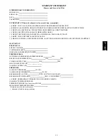
Table 15 – Troubleshooting Guide–LED Status Codes
SYMPTOM
CAUSE
REMEDY
No Power Hardware failure
(LED OFF)
Loss of power to control module (IGC)*.
Check 5--amp fuse son IGC*, power to unit, 24--v circuit breaker,
and transformer. Units without a 24--v circuit breaker have an
internal overload in the 24--v transformer. If the overload trips,
allow 10 minutes for automatic reset.
Check fuse, low voltage cir-
cuit
(LED 1 flash)
Fuse is blown or missing or short circuit in secondary
(24VAC) wiring.
Replace fuse if needed. Verify no short circuit in low voltage (24
VAC wiring).
Limit switch faults
(LED 2 flashes)
High temperature limit switch is open.
Check the operation of the indoor (evaporator) fan motor. Ensure
that the supply--air temperature rise is in accordance with the
range on the unit nameplate. Clean or replace filters.
Flame sense fault
(LED 3 flashes)
The IGC* sensed flame that should not be present.
Reset unit. If problem persists, replace control board.
4 consecutive limit switch
faults
(LED 4 flashes)
Inadequate airflow to unit.
Check the operation of the indoor (evaporator) fan motor and that
supply--air temperature rise agrees with range on unit nameplate
information.
Ignition lockout
(LED 5 flashes)
Unit unsuccessfully attempted ignition for 15 minutes.
Check ignitor and flame sensor electrode spacing, gaps, etc.
Ensure that fame sense and ignition wires are properly terminated.
Verify that unit is obtaining proper amount of gas.
Pressure Switch motor fault
(LED 6 flashes)
Open pressure switch.
Verify wiring connections to pressure switch and inducer motor.
Verify pressure switch hose is tightly connected to both inducer
housing and pressure switch. Verify inducer wheel is properly
attached to inducer motor shaft. Verify inducer motor shaft is turn-
ing.
Rollout switch fault
(LED 7 flashes)
Rollout switch has opened.
Rollout switch will automatically reset, but IGC* will continue to
lockout unit. Check gas valve operation. Ensure that induced--draft
blower wheel is properly secured to motor shaft. Inspect heat
exchanger. Reset unit at unit disconnect.
Internal control fault
(LED 8 flashes)
Microprocessor has sensed an error in the software
or hardware.
If error code is not cleared by resetting unit power, replace the
IGC*.
Temporary 1 hr auto reset
(LED 9 flashes)
Electrical interference impeding IGC software
Reset 24--v. to control board or turn thermostat off, then on again.
Fault will automatically reset itself in one (1) hour.
IMPORTANT
: Refer to Table 14---Troubleshooting Guide---Heating for additional troubleshooting analysis.
LEGEND
IGC—Integrated Gas Unit Controller
LED—Light---Emitting Diode
ELECTROSTATIC DISCHARGE (ESD) PRECAUTIONS PROCEDURE RELIABILITY HAZARD
Failure to follow this caution may result in unit component damage.
Electrostatic discharge can affect electronic components. Take precautions during furnace installation and servicing to protect the furnace
electronic control. Precautions will prevent electrostatic discharges from personnel and hand tools which are held during the procedure.
These precautions will help to avoid exposing the control to electrostatic discharge by putting the furnace, the control, and the person at
the same electrostatic potential.
CAUTION
!
677C
--
--
C
Summary of Contents for Legacy 677C**C Series
Page 3: ...3 A150538 Fig 2 24 30 Unit Dimensions 677C C...
Page 4: ...4 A150539 Fig 3 36 60 Unit Dimensions 677C C...
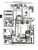
Page 44: ...44 A150506 Fig 15 208 230 1 60 Connection Wiring Diagram 677C C...
Page 45: ...45 A150516 Fig 15 Cont 208 230 1 60 Ladder Wiring Diagram 677C C...
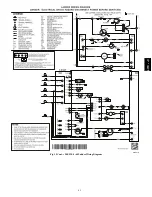
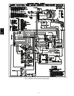
Page 46: ...46 A150507 Fig 16 208 230 3 60 Connection Wiring Diagram 677C C...
Page 47: ...47 A150517 Fig 16 Cont 208 230 3 60 Ladder Wiring Diagram 677C C...


