background image

7

Training for operators of the lifting equipment should include, but
not be limited to, the following:

1. Application of the lifter to the load, and adjustment of the

lifts to adapt to various sizes or kinds of loads.

2. Instruction in any special operation or precaution.
3. Condition of the load as it relates to operation of the lifting

kit, such as balance, temperature, etc.

Follow all applicable safety codes. Wear safety shoes and work

gloves.

Inspection

Prior to initial use, and at monthly intervals, all rigging shackles,

clevis pins, and straps should be visually inspected for any

damage, evidence of wear, structural deformation, or cracks.
Particular attention should be paid to excessive wear at hoist

hooking points and load support areas. Materials showing any kind
of wear in these areas must not be used and should be discarded.
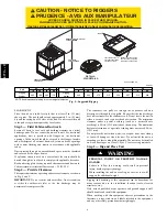
UNIT FALLING HAZARD

Failure to follow this warning could result in personal

injury or death.
Never stand beneath rigged units or lift over people.

!

WARNING

PROPERTY DAMAGE HAZARD

Failure to follow this warning could result in personal

injury/death or property damage.
When straps are taut, the clevis should be a minimum of 36

in. (914 mm) above the unit top cover.

!

WARNING

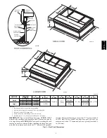
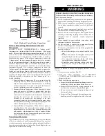
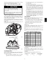
Rigging/Lifting of Unit (See Fig. 5)

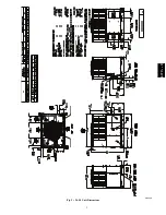
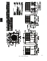
Lifting holes are provided in base rails as shown in Fig. 2 and 3.

1. Leave top shipping skid on the unit for use as a spreader bar

to prevent the rigging straps from damaging the unit. If the

skid is not available, use a spreader bar of sufficient length
to protect the unit from damage.

2. Attach shackles, clevis pins, and straps to the base rails of

the unit. Be sure materials are rated to hold the weight of the
unit (See Fig. 5).

3. Attach a clevis of sufficient strength in the middle of the

straps. Adjust the clevis location to ensure unit is lifted level

with the ground.

After the unit is placed on the roof curb or mounting pad, remove
the top skid.

Step 6 — Connect Condensate Drain

NOTE

: When installing condensate drain connection be sure to

comply with local codes and restrictions.
Unit disposes of condensate water through a 3/4 in. NPT fitting
which exits through the compressor access panel (See Fig. 2 and 3

for location).
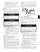
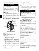
Condensate water can be drained directly onto the roof in rooftop

installations (where permitted) or onto a gravel apron in ground
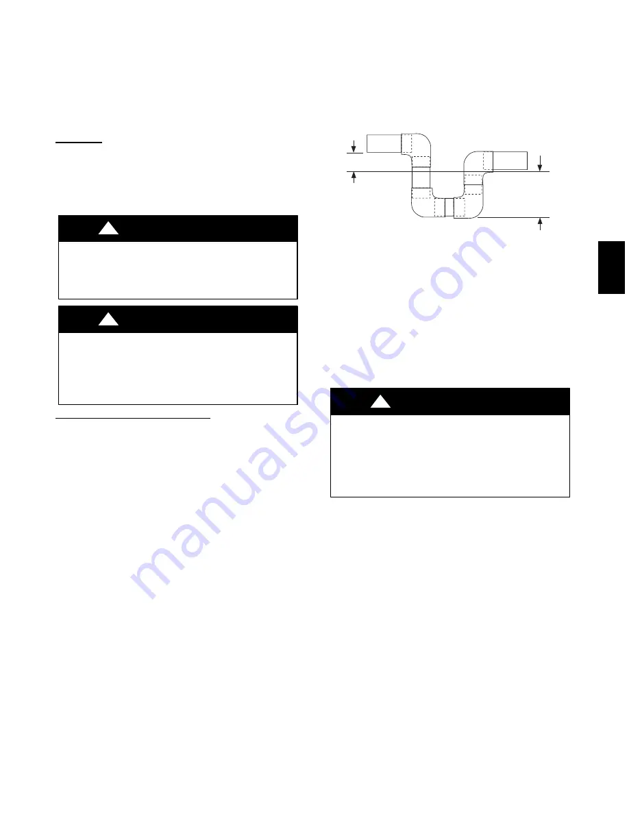
level installations. Install a field--supplied condensate trap at end

of condensate connection to ensure proper drainage. Make sure that

the outlet of the trap is at least 1 in. (25 mm) lower than the

drain--pan condensate connection to prevent the pan from

overflowing (See Fig. 6). Prime the trap with water. When using a
gravel apron, make sure it slopes away from the unit.
If the installation requires draining the condensate water away

from the unit, install a 2--in. (51 mm) trap at the condensate
connection to ensure proper drainage (See Fig. 6). Make sure that

the outlet of the trap is at least 1 in. (25 mm) lower than the
drain--pan condensate connection. This prevents the pan from

overflowing.
Prime the trap with water. Connect a drain tube -- using a minimum

of 3/4--in. PVC or 3/4--in. copper pipe (all field--supplied) -- at the

outlet end of the 2--in. (51 mm) trap. Do not undersize the tube.
Pitch the drain tube downward at a slope of at least 1--in. (25 mm)

for every 10 ft (3 m) of horizontal run. Be sure to check the drain
tube for leaks.

TRAP
OUTLET

1-in. (25 mm) min.

2-in. (51 mm) min.

A09052

Fig. 6 -- Condensate Trap

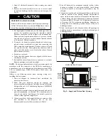
Step 7 — Install Flue Hood

The flue assembly is secured and shipped in the return air duct.

Remove duct cover to locate the assembly (See Fig. 8).

NOTE

:

Dedicated low NOx models MUST be installed in

California Air Quality Management Districts where a Low NOx
rule exists.
These models meet the California maximum oxides of nitrogen
(NOx) emissions requirements of 40 nanograms/joule or less as

shipped from the factory.

NOTE

:

Low NOx requirements apply only to natural gas

installations.

CARBON MONOXIDE POISONING HAZARD

Failure to follow this warning could result in personal

injury or death.
The venting system is designed to ensure proper venting.

The flue hood assembly must be installed as indicted in this

section of the unit installation instructions.

!

WARNING

Install the flue hood as follows:

1. This installation must conform with local building codes

and with the National Fuel Gas Code (NFGC) NFPA 54 /
ANSI Z223.1,

(in Canada, CAN/CSA B149.1, and

B149.2) latest revision. Refer to Provincial and local
plumbing or wastewater codes and other applicable local
codes.

2. Remove flue hood from shipping location (inside the return

section of the blower compartment--see Fig. 8). Remove the

return duct cover to locate the flue hood. Place flue hood
assembly over flue panel. Orient screw holes in flue hood
with holes in the flue panel.

3. Secure flue hood to flue panel by inserting a single screw on

the top flange and the bottom flange of the hood.

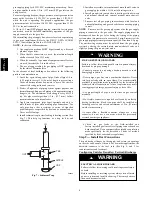
Step 8 — Install Gas Piping

The gas supply pipe enters the unit through the access hole
provided. The gas connection to the unit is made to the 1/2--in.

(12.7 mm) FPT gas inlet on the gas valve.
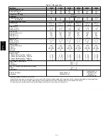
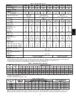
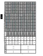
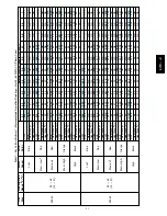
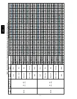
Install a gas supply line that runs to the heating section. Refer to

Table 2 and the NFGC for gas pipe sizing. Do not use cast--iron

pipe. It is recommended that a black iron pipe is used. Check the
local utility for recommendations concerning existing lines. Size

677C

--

--

C

Summary of Contents for Legacy 677C**C Series

Page 1: ...lower and Motor 49 Flue Gas Passageways 50 Limit Switch 50 Burner Ignition 50 Main Burners 50 Outdoor Coil Indoor Coil Condensate Drain Pan 50 A09034 Fig 1 Unit 677C C Outdoor Fan 51 Electrical Contro...

Page 2: ...ment IDENTIFY UNIT The unit model number and serial number are stamped on the unit information plate Check this information against shipping papers INSPECT SHIPMENT Inspect for shipping damage before...

Page 3: ...3 A150538 Fig 2 24 30 Unit Dimensions 677C C...

Page 4: ...4 A150539 Fig 3 36 60 Unit Dimensions 677C C...

Page 5: ...S 1 Roof curb must be set up for unit being installed 2 Seal strip must be applied as required to unit being installed 3 Roof curb is made of 16 gauge steel 4 Attach ductwork to curb flanges of duct r...

Page 6: ...oof deck to comply with applicable fire codes Read unit rating plate for any required clearances around ductwork Cabinet return air static shall not exceed 25 IN W C Step 4 Provide Clearances The requ...

Page 7: ...pan from overflowing See Fig 6 Prime the trap with water When using a gravel apron make sure it slopes away from the unit If the installation requires draining the condensate water away from the unit...

Page 8: ...ll ground joint union close to heating section between unit manual shutoff and external manual main shut off valve 7 Pressure test all gas piping in accordance with local and national plumbing and gas...

Page 9: ...or local codes and ordinances Adhere to the following criteria when selecting sizing and installing the duct system 1 Units are shipped for horizontal duct installation by removing duct covers 2 Sele...

Page 10: ...4 x 254 1 2 800 10 x 10 254 x 254 1 2 1000 10 x 10 254 x 254 1 2 1000 10 x 10 254 x 254 1 2 1200 11 x 10 279 x 254 1 2 1200 11 x 10 279 x 254 1 2 Furnace Section Burner Orifice 1 Phase Natural Gas Qty...

Page 11: ...24x15x1 610x406x25 1 each 24x16x1 610x406x25 24x18x1 610x457x25 Based on altitude of 0 to 2000 ft 0 610 m Required filter sizes shown are based on the larger of the AHRI Air Conditioning Heating and...

Page 12: ...unit gas combustion supply air louvers See unit wiring label Fig 15 and 16 and Fig 9 for reference when making high voltage connections Proceed as follows to complete the high voltage connections to t...

Page 13: ...his point the indoor supply air feels uncomfortable i e too cool This is purely subjective and will depend on the homeowner s idea of comfort Below this temperature the gas furnace should operate in o...

Page 14: ...point thermostat closes circuits R to G R to Y and R to O The unit delivers cooling airflow c HEAT PUMP HEATING MODE Outdoor temperature above balance point setpoint of thermostat 1 On a call for heat...

Page 15: ...ol break the 24 v power to W 5 The evaporator fan will turn on 45 sec after the flame has been established The evaporator fan will turn off 45 sec after the thermostat has been satisfied Please note t...

Page 16: ...e in the manifold pressure is required Observe manifold pressure and proceed as follows to adjust gas input 1 Remove regulator cover screw over plastic adjustment screw on gas valve See Fig 12 2 Turn...

Page 17: ...on When turning backwards the difference between compressor suction and discharge pressures will be near zero Checking and Adjusting Refrigerant Charge The refrigerant system is fully charged with Pur...

Page 18: ...e current speed tap wire from the GAS HEAT terminal on the interface fan board IFB Fig 14 and place vinyl cap over the connector on the wire 3 Connect the desired speed tap wire to the GAS HEAT termin...

Page 19: ...ed Low Speed Blue Low Speed DH DH DH DH DH DH DH DH Shunt in no dehumidification position Shunt in dehumidification position A14399 Fig 13 Single Phase IGC Board COM LOW HIGH GAS HEAT Q1 R1L C8 RL3 Q3...

Page 20: ...28 NA NA High Black CFM 1187 1124 1061 996 930 896 840 776 698 610 BHP 0 36 0 36 0 37 0 37 0 38 0 38 0 39 0 39 0 39 0 40 Heat Rise o F 25 26 28 30 32 33 35 38 43 49 Heat Rise o C 14 15 16 17 18 18 20...

Page 21: ...6 28 NA NA High Black CFM 1187 1124 1061 996 930 896 840 776 698 610 BHP 0 36 0 36 0 37 0 37 0 38 0 38 0 39 0 39 0 39 0 40 Heat Rise o F 25 26 28 30 32 33 35 38 43 49 Heat Rise o C 14 15 16 17 18 18 2...

Page 22: ...30 High Black CFM 1602 1535 1469 1404 1333 1260 1246 1192 1191 1131 BHP 0 46 0 47 0 48 0 50 0 50 0 51 0 52 0 53 0 54 0 55 Heat Rise o F 28 29 31 32 34 36 36 38 38 40 Heat Rise o C 16 16 17 18 19 20 2...

Page 23: ...24 High Black CFM 1575 1528 1488 1447 1406 1360 1314 1264 1213 1159 BHP 0 40 0 42 0 43 0 44 0 45 0 46 0 47 0 48 0 49 0 50 Heat Rise o F 28 29 30 31 32 33 34 35 37 39 Heat Rise o C 16 16 17 17 18 18 1...

Page 24: ...25 High Black CFM 2267 2201 2133 2071 1997 1923 1835 1739 1654 1551 BHP 1 03 1 00 0 97 0 93 0 89 0 86 0 82 0 78 0 74 0 69 Heat Rise o F NA NA NA NA NA 35 37 39 41 44 Heat Rise o C NA NA NA NA NA 20 2...

Page 25: ...36 High Black CFM 2267 2201 2133 2071 1997 1923 1835 1739 1654 1551 BHP 1 03 1 00 0 97 0 93 0 89 0 86 0 82 0 78 0 74 0 69 Heat Rise o F 42 44 45 46 48 50 52 55 58 62 Heat Rise o C 24 24 25 26 27 28 2...

Page 26: ...41 0 42 0 43 0 45 0 45 Heat Rise o F 59 60 NA NA NA NA NA NA NA NA Heat Rise o C 33 33 NA NA NA NA NA NA NA NA Medium 2 Red CFM 1736 1710 1668 1630 1600 1557 1522 1479 1450 1406 BHP 0 53 0 54 0 55 0...

Page 27: ...62 0 63 0 64 0 65 Heat Rise o F 55 56 57 59 60 62 63 65 NA NA Heat Rise o C 31 31 32 33 33 34 35 36 NA NA Med High 1 Orange CFM 1935 1909 1867 1836 1808 1766 1696 1619 1535 1454 BHP 0 71 0 73 0 74 0...

Page 28: ...48 52 Heating Rise o C 18 19 20 21 22 23 25 27 29 High Black CFM 1536 1470 1405 1333 1263 1204 1239 1181 1122 Heating Rise o F 28 29 31 33 34 36 35 37 39 Heating Rise o C 16 16 17 18 19 20 19 20 21 36...

Page 29: ...44 47 50 Heating Rise o C 18 19 19 20 22 23 24 26 28 High Black CFM 1472 1401 1326 1251 1275 1198 1139 1085 1023 Heating Rise o F 29 31 33 35 34 36 38 40 42 Heating Rise o C 16 17 18 19 19 20 21 22 2...

Page 30: ...35 36 37 Heating Rise o C NA NA NA NA NA NA 20 20 21 High Black CFM 2344 2306 2259 2203 2141 2070 1991 1902 1803 Heating Rise o F NA NA NA NA NA NA NA 35 37 Heating Rise o C NA NA NA NA NA NA NA 20 2...

Page 31: ...50 51 53 Heating Rise o C 25 25 26 26 27 27 28 28 29 High Black CFM 2344 2306 2259 2203 2141 2070 1991 1902 1803 Heating Rise o F 41 41 42 43 44 46 48 50 53 Heating Rise o C 23 23 23 24 25 26 27 28 2...

Page 32: ...o F 19 36 o C Low Blue CFM 1445 1389 1341 1281 1236 1189 1139 1072 1027 Heating Rise o F NA NA NA NA NA NA NA NA NA Heating Rise o C NA NA NA NA NA NA NA NA NA Med Low Pink CFM 1678 1635 1602 1558 151...

Page 33: ...NA NA NA NA NA NA NA Heating Rise o C 24 27 29 NA NA NA NA NA NA NA Medium 2 Red CFM 1222 1236 1195 1148 1101 1052 1004 957 916 868 WATTS 233 221 232 244 251 264 275 285 291 304 BHP 0 25 0 24 0 25 0...

Page 34: ...NA NA NA NA NA NA NA Heating Rise o C NA NA NA NA NA NA NA NA NA NA Medium 2 Red CFM 1222 1236 1195 1148 1101 1052 1004 957 916 868 WATTS 256 270 283 289 301 313 320 331 343 349 BHP 0 27 0 29 0 30 0 3...

Page 35: ...F 43 46 49 53 NA NA NA NA NA NA Heating Rise o C 24 26 27 29 NA NA NA NA NA NA Medium Red CFM 1255 1210 1145 1074 1008 940 878 895 838 785 WATTS 249 272 284 292 305 319 320 329 336 347 BHP 0 27 0 29 0...

Page 36: ...NA NA NA NA NA NA NA NA NA NA Heating Rise o C NA NA NA NA NA NA NA NA NA NA Medium 1 Red CFM 1255 1210 1145 1074 1008 940 878 895 838 785 WATTS 249 272 284 292 305 319 320 329 336 347 BHP 0 27 0 29 0...

Page 37: ...o F 43 44 46 47 48 50 51 53 55 57 Heating Rise o C 24 25 25 26 27 28 29 30 30 32 Medium 2 Red CFM 1861 1822 1786 1758 1716 1688 1660 1619 1583 1539 WATTS 400 417 426 441 452 467 482 492 507 519 BHP 0...

Page 38: ...F 55 56 58 59 NA NA NA NA NA NA Heating Rise o C 30 31 32 33 NA NA NA NA NA NA Medium 2 Red CFM 1861 1822 1786 1758 1716 1688 1660 1619 1583 1539 WATTS 400 417 426 441 452 467 482 492 507 519 BHP 0 4...

Page 39: ...F 61 63 65 NA NA NA NA NA NA NA Heating Rise o C 34 35 36 NA NA NA NA NA NA NA Medium 2 Red CFM 1861 1822 1786 1758 1716 1688 1660 1619 1583 1539 WATTS 400 417 426 441 452 467 482 492 507 519 BHP 0 4...

Page 40: ...e o F 36 37 38 39 40 41 41 42 44 45 Heating Rise o C 20 21 21 22 22 23 23 24 24 25 Medium 2 Red CFM 1944 1913 1872 1838 1801 1771 1731 1698 1655 1613 WATTS 486 501 511 529 537 554 565 578 595 603 BHP...

Page 41: ...o F 46 47 48 49 50 52 53 54 56 58 Heating Rise o C 26 26 27 27 28 29 29 30 31 32 Medium 2 Red CFM 1944 1913 1872 1838 1801 1771 1731 1698 1655 1613 WATTS 486 501 511 529 537 554 565 578 595 603 BHP 0...

Page 42: ...57 0 58 0 59 0 61 0 62 0 64 0 65 Heating Rise o F 49 50 51 52 53 54 55 56 58 59 Heating Rise o C 27 28 28 29 29 30 31 31 32 33 Med High 1 Orange CFM 2178 2148 2105 2073 2036 2002 1967 1919 1845 1751...

Page 43: ...00 1200 1300 1400 1500 1600 1700 1800 1900 2000 2100 2200 24 0 03 0 04 0 04 0 05 0 06 30 0 05 0 06 0 07 0 08 0 11 36 0 06 0 06 0 09 0 10 0 11 0 14 42 0 05 0 05 0 06 0 07 0 08 0 08 0 09 0 09 0 11 48 0...

Page 44: ...44 A150506 Fig 15 208 230 1 60 Connection Wiring Diagram 677C C...

Page 45: ...45 A150516 Fig 15 Cont 208 230 1 60 Ladder Wiring Diagram 677C C...

Page 46: ...46 A150507 Fig 16 208 230 3 60 Connection Wiring Diagram 677C C...

Page 47: ...47 A150517 Fig 16 Cont 208 230 3 60 Ladder Wiring Diagram 677C C...

Page 48: ...under these conditions using the superheat method Weigh in method should be used A150625 To properly check or adjust charge conditions must be favorable for subcooling charging Favorable conditions e...

Page 49: ...pect heating section before each heating season Clean and adjust when necessary 6 Check flue hood and remove any obstructions if necessary Air Filter IMPORTANT Never operate the unit without a suitabl...

Page 50: ...tation If lockout occurs unit may be reset by either momentarily interrupting power supply to unit or by turning selector switch to OFF position at the thermostat Main Burners At the beginning of each...

Page 51: ...hen the electrical power to the unit Remove access panels see Fig 19 to locate all the electrical controls and wiring Check all electrical connections for tightness Tighten all screw connections If an...

Page 52: ...the liquid line and protects against low suction pressures caused by such events as loss of charge low airflow across indoor coil dirty filters etc It opens on a pressure drop at about 20 psig If syst...

Page 53: ...TOR THERMOSTAT INPUTS T1 ENABLES DEFROST TIMER MUST BE ENERGIZED FOR DEFROST TIMER TO START C COMMON O REVERSING VALVE SPEEDUP DEFROST THERMOSTAT MUST BE CLOSED BEFORE DEFROST TIMER BEGINS A150622 Fig...

Page 54: ...NDOOR COIL LCS LEGEND HPS High Pressure Switch LCS Loss of Charge Switch Accurater Metering Device Arrow indicates direction of flow TXV in Metering Position Bypass Position HPS C03011 Fig 26 Typical...

Page 55: ...ing to occur in one year or more When performing any service that may risk exposure of compressor oil to the roof take appropriate precautions to protect roofing Procedures which risk oil leakage incl...

Page 56: ...old sets should be minimum 700 psig high side and 180 psig low side with 550 psig low side retard S Use hoses with minimum 700 psig service pressure rating S Leak detectors should be designed to detec...

Page 57: ...restriction and remove Compressor operates continuously Dirty air filter Replace filter Unit undersized for load Decrease load or increase unit size Thermostat set too low Reset thermostat Low refrig...

Page 58: ...ise is in accordance with the range on the unit nameplate Clean or replace filters Flame sense fault LED 3 flashes The IGC sensed flame that should not be present Reset unit If problem persists replac...

Page 59: ...N IS LEVEL CHECK FAN WHEEL AND PROPELLER FOR LOCATION IN HOUSING ORIFICE AND SETSCREW TIGHTNESS III START UP ELECTRICAL SUPPLY VOLTAGE COMPRESSOR AMPS INDOOR EVAPORATOR FAN AMPS TEMPERATURES OUTDOOR C...

Page 60: ...ntinue or change at any time specifications or designs without notice and without incurring obligations E2015 Bryant Heating Cooling Systems D 7310 W Morris St D Indianapolis IN 46231 Edition Date 12...

Reviews: