707C--K: Installation Instructions
Manufacturer reserves the right to change, at any time, specifications and designs without notice and without obligations.
28
Rotary Compressor
The 24 and 30 size units use a single cylinder rotary compressor. This
compressor utilizes a rotor which is positioned eccentrically with respect
to the shell. Refrigerant gas is ported directly into the compression
chamber and discharged into the surrounding area. It is also known as a
“high-side” design since high pressure gas surrounds the motor and
compression chamber. The majority of the shell will be hot to the touch.
The rotary compressor also utilizes an external built-in accumulator to
reduce the likelihood of refrigerant liquid from entering the compressor.
Servicing Systems on Roofs with Synthetic Materials
POE (polyolester) compressor lubricants are known to cause long term
damage to some synthetic roofing materials. Exposure, even if
immediately cleaned up, may cause embrittlement (leading to cracking)
to occur in one year or more. When performing any service that may risk
exposure of compressor oil to the roof, take appropriate precautions to
protect roofing. Procedures which risk oil leakage include, but are not
limited to, compressor replacement, repairing refrigerant leaks, replacing
refrigerant components such as filter drier, pressure switch, metering
device, coil, accumulator, or reversing valve.
Synthetic Roof Precautionary Procedure
1. Cover extended roof working area with an impermeable
polyethylene (plastic) drip cloth or tarp. Cover an approximate 10 x
10 ft (3 x 3 m) area.
2. Cover area in front of the unit service panel with a terry cloth shop
towel to absorb lubricant spills, prevent run-offs, and protect drop
cloth from tears caused by tools or components.
3. Place terry cloth shop towel inside unit immediately under
component(s) to be serviced and prevent lubricant run-offs through
the louvered openings in the unit base.
4. Perform required service.
5. Remove and dispose of any oil contaminated material per local
codes.
Liquid Line Filter Drier
The filter drier is specifically designed to operate with Puron (R-410A).
Use only factory-authorized components. Filter drier must be replaced
whenever the refrigerant system is opened. When removing a filter drier,
use a tubing cutter to cut the drier from the system. Do not unsweat a
filter drier from the system. Heat from unsweating will release moisture
and contaminants from drier into system.
Puron (R-410A) Refrigerant Charging
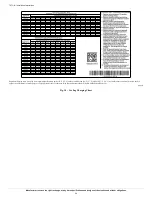
Refer to unit information plate and charging chart. Some R-410A
refrigerant cylinders contain a dip tube to allow liquid refrigerant to flow
from cylinder in upright position. For cylinders equipped with a dip tube,
charge Puron (R-410A) units with cylinder in upright position and a
commercial metering device in manifold hose. Charge refrigerant into
suction-line.
Troubleshooting
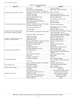
Refer to the Troubleshooting Chart (
) for troubleshooting
information.
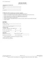
Start-up Checklist
Use the Start-Up Checklist at the back of this manual.
My Learing Cener is your central location for professional residential
HVAC training resources that help strengthen careers and businesses.
We believe in providing high quality learning experiences both online
and in the classroom.
Access My Learning Center with your HVACpartners credentials at
. Please contact us at
mylearning@carrier.com
with questions.


