background image

17

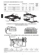
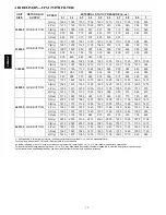
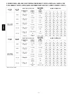
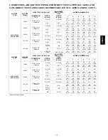
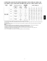
COMBUSTION--AIR AND VENT PIPING FOR DIRECT VENT/2--PIPE (ALL SIZES) AND

NON--DIRECT VENT/1--PIPE (SIZES 040 THROUGH 120 ONLY) APPLICATIONS (CON’T.)

ALTITUDE

FT (M)

UNIT SIZE

(BTUH)

DIRECT VENT (2-PIPE) ONLY

NON-DIRECT

VENT (1-PIPE)

ONLY

NUMBER OF 90

°

ELBOWS

TERMINATION

TYPE

PIPE DIA

IN. (mm)*

PIPE DIA

IN. (mm)*

1

2

3

4

5

6

9001 to 10,000‡

(2743 to 3048)

40,000

2 Pipe or 2-in

1-1/2 (38)

1-1/2 (38)

42

(12.8)

37

(11.3)

32

(9.8)

27

(8.2)

25

(7.6)

20

(6.1)

Concentric

2 (51)

2 (51)

57

(17.4)

55

(16.8)

53

(16.2)

51

(15.5)

49

(14.9)

47

(14.3)

60,000

2 Pipe or 2-in

Concentric

2 (51)

2 (51)

45

(13.7)

40

(12.2)

38

(11.6)

33

(10.1)

31

(9.4)

29

(8.8)

80,000

2 Pipe or 2-in

Concentric

2 (51)

2 (51)

30

(9.1)

25

(7.6)

14

(4.3)

9

(2.7)

7

(2.1)

NA

2-1/2 (64)

2-1/2 (64)

57

(17.4)

55

(16.8)

53

(16.2)

51

(15.5)

49

(14.9)

47

(14.3)

100,000

2 Pipe or 3-in

Concentric

2-1/2 (64)

2-1/2 (64)

21

(6.4)

13

(4.0)

5

(1.5)

NA

NA

NA

3 (76)

3 (76)

54

(16.5)

49

(14.9)

44

(13.4)

39

(11.9)

34

(10.4)

29

(8.8)

120,000

2 Pipe or 3-in.

Concentric

NA

3 (76)†

39

(11.9)

37

(11.3)

35

(10.7)

33

(10.1)

31

(9.4)

29

(8.8)

4 (102)† no

disk

4 (102)† no disk

10

(3.0)

5

(1.5)

NA

NA

NA

NA

* Disk usage-Unless otherwise specified, use perforated disk assembly (factory-supplied in loose parts bag).
# If one disk is stated, separate 2 halves of perforated disk assembly and use shouldered disk half. When using shouldered disk half, install screen side toward inlet box.
† Wide radius elbow.
‡ Vent sizing for Canadian installations over 4500 ft (1370 M) above sea level are subject to acceptance by the local authorities having jurisdiction. NA-Not Allowed;

pressure switch will not make.

NOTES

:

1. Do not use pipe size greater than those specified in table or incomplete combustion, flame disturbance, or flame sense lockout may occur.
2. Size both the combustion-air and vent pipe independently, then use the larger diameter for both pipes.
3. Assume two 45

°

elbows equal one 90

°

elbow. Wide radius elbows are desirable and may be required in some cases.

4. Elbows and pipe sections within the furnace casing and at the vent termination should not be included in vent length or elbow count.
5. The minimum pipe length is 5 ft (1.5 M) for all applications.
6. Use 3-in. (76 mm) diameter vent termination kit for installations requiring 4-in (102 mm) diameter pipe.

353AA

V

Summary of Contents for PLUS 90X 353AAV

Page 1: ...oning Boosting the unit s efficiency with the ECM motor and Bryant s deluxe features show the Plus 90x has been designed with the homeowner in mind PLUS 90X FEATURES BENEFITS EverlasticTM Exclusive Ev...

Page 2: ...smooth quiet combustion plus economical gas usage Slow Opening Redundant Gas Valve Shuts off gas to burners if any of the valves fails to close completely for any reason The slow opening feature reduc...

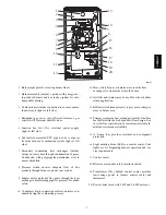
Page 3: ...motor pulls hot flue gases through the heat exchangers maintaining negative pressure for added safety 10 Condensate drain connection collects moisture con densed during the combustion process 1 2 3 4...

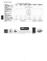
Page 4: ...NITION DEVICE Hot Surface DIRECT DRIVE MOTOR ECM X 13 1 2 1 2 1 2 3 4 1 1 MOTOR FULL LOAD AMPS 6 8 6 8 6 8 8 4 10 9 10 9 RPM Nominal SPEEDS 1050 5 BLOWER WHEEL DIAMETER X WIDTH IN mm 10 X 7 254 X 178...

Page 5: ...For use with multi use stage configurations deg F C Auto Changeover Temperature and Humidity Control T6 PRH THERMOSTAT PROGRAMMABLE For use with 1 speed Air Conditioner deg F C Auto Changeover 7 Day...

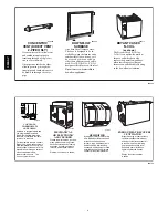
Page 6: ...dirt and many pollens commonly found Saves decorating and cleaning expenses by keeping carpets furniture and drapes cleaner Electronic air cleaner is shown A97432 CONTROLS THERMOSTATS AND ZONING Avai...

Page 7: ...t furnace a For 800 CFM 16 in 406mm round or 14 1 2 368mm x 12 in 305mm rectangle b For 1200 CFM 20 in 508mm round or 14 1 2 368mm x 19 1 2 in 495mm rectangle c For 1600 CFM 22 in 559mm round or 14 1...

Page 8: ...IPE APPLICATION SIZES 040 THROUGH 120 ONLY LENGTH OF STRAIGHT PIPE PORTION OF COMBUSTION AIR INLET PIPE ASSEMBLY IN mm CASING WIDTH A 17 1 2 8 1 2 1 2 216 13 mm 21 533 mm 10 1 2 1 2 267 13 mm 24 1 2 6...

Page 9: ...5 635 24 610 23 5 8 600 mm 23 3 8 594 mm Furnace Side 23 3 4 603 mm Centerline Screw Slots 25 5 8 651 mm Duct Side 24 3 8 619 mm Opening with Flanges Bent 23 1 8 587 mm Opening 5 3 4 146 mm g n i n e...

Page 10: ...10 CLEARANCE TO COMBUSTIBLES 335122 201 REV B LIT TOP A08435 353AAV...

Page 11: ...39 30 60 17 33 30 60 17 33 40 70 22 39 CERTIFIED EX STATIC PRESSURE in wc Heating 0 10 0 12 0 15 0 15 0 20 0 20 Cooling 0 50 0 50 0 50 0 50 0 50 0 50 AIRFLOW CFM Heating 845 1040 1180 1450 1890 2065...

Page 12: ...970 2 Org 1210 1180 1135 1085 1035 995 950 910 865 810 048080 SIDE BOTTOM 1 Red 1110 1065 1005 960 910 865 820 770 720 670 5 Gry 2070 2020 1985 1925 1890 1850 1795 1755 1690 1610 3 Blu 1815 1775 1730...

Page 13: ...ric 2 1 2 64 one disk 2 1 2 64 10 3 0 NA NA NA NA NA 3 76 NA 45 13 7 40 12 2 35 10 7 30 9 1 25 7 6 20 6 1 3 76 no disk 3 76 70 21 3 70 21 3 70 21 3 70 21 3 70 21 3 70 21 3 ALTITUDE FT M UNIT SIZE BTUH...

Page 14: ...3 4 38 11 6 31 9 4 NA 3 76 59 18 0 59 18 0 58 17 7 57 17 4 57 17 4 56 17 1 4 no disk 4 102 no disk 4 102 no disk 70 21 3 70 21 3 70 21 3 70 21 3 70 21 3 70 21 3 ALTITUDE FT M UNIT SIZE BTUH DIRECT VEN...

Page 15: ...ntric 3 76 no disk NA 42 12 8 35 10 7 29 8 8 22 6 7 15 4 6 9 2 7 NA 3 76 53 16 2 52 15 8 50 15 2 49 14 9 48 14 6 47 14 3 4 102 no disk 4 102 no disk 70 21 3 70 21 3 70 21 3 70 21 3 70 21 3 70 21 3 ALT...

Page 16: ...A 20 6 1 13 4 0 7 2 1 NA NA NA NA 3 76 46 14 0 44 13 4 43 13 1 41 12 5 40 12 2 38 11 6 4 102 no disk 4 102 no disk 61 18 6 56 17 1 51 15 5 46 14 0 41 12 5 36 11 0 ALTITUDE FT M UNIT SIZE BTUH DIRECT V...

Page 17: ...isk 10 3 0 5 1 5 NA NA NA NA Disk usage Unless otherwise specified use perforated disk assembly factory supplied in loose parts bag If one disk is stated separate 2 halves of perforated disk assembly...

Page 18: ...7 2 51 55 17 55 17 0 18 2 51 48 15 55 17 20 29 2 51 30 9 55 17 20 7 2 5 64 70 21 70 21 0 18 2 5 64 47 14 70 21 20 29 2 5 64 28 9 70 21 100 20 7 2 5 64 40 12 40 12 0 18 2 5 64 40 12 40 12 20 29 2 5 64...

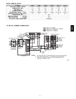
Page 19: ...Standard TYPICAL WIRING SCHEMATIC 115 V FIELD SUPPLIED DISCONNECT AUXILIARY J BOX 24 V TERMINAL BLOCK THREE WIRE HEATING ONLY FIVE WIRE NOTE 1 NOTE 2 FIELD SUPPLIED DISCONNECT CONDENSING UNIT TWO WIR...

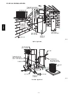
Page 20: ...CTRONIC AIR CLEANER AIRFLOW FRONT OF FURNACE COMBUSTION AIR INLET NON DIRECT 1 PIPE APPLICATION A05064 Upflow Application ELECTRONIC AIR CLEANER HUMIDIFIER A C COIL VENT COMBUSTION AIR DIRECT VENT 2 P...

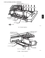
Page 21: ...VENT 2 PIPE APPLICATION COMBUSTION AIR INLET NON DIRECT VENT 1 PIPE APPLICATION A05066 Attic Horizontal Application COMBUSTION AIR PIPE DIRECT VENT 2 PIPE APPLICATION VENT PIPE ELECTRONIC AIR CLEANER...

Page 22: ...ion ______________Media Filter Casing Casing shall be of 030 in 03 mm thickness minimum pre painted galvanized steel Inducer Motor Inducer motor shall be soft mounted to reduce vibration transmission...

Reviews: