background image


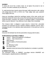
1) SAFETY 

This manual contains information and warnings that must be followed for operating the 
instrument  safely  and  maintaining  the  instrument  in  a  safe  operating  condition.  If  the 
instrument  is  used  in  a  manner  not  specified  by  the  manufacturer,  the  protection 
provided by the instrument may be impaired.   
 
The meter protection rating, against the users, is double insulation per IEC61010-1 2nd 
Ed., EN61010-1 2nd Ed., UL61010-1 2nd Ed., CAN/CSA C22.2 No. 61010-1, 2nd Ed., 
IEC61010-2-032,  EN61010-2-032,  UL61010B-2-032  and  CAN/CSA  C22.2  No. 
61010-2-032-04:   
 
Category CAT III 600V AC & DC. 
 

PER IEC61010 OVERVOLTAGE INSTALLATION CATEGORY 

OVERVOLTAGE CATEGORY II 

Equipment  of  OVERVOLTAGE  CATEGORY  II  is  energy-consuming  equipment  to  be 
supplied from the fixed installation. 
Note – Examples include household, office, and laboratory appliances. 

OVERVOLTAGE CATEGORY III 

Equipment of OVERVOLTAGE CATEGORY III is equipment in fixed installations. 
Note  –  Examples  include  switches  in  the  fixed  installation  and  some  equipment  for 
industrial use with permanent connection to the fixed installation. 

OVERVOLTAGE CATEGORY IV 

Equipment  of  OVERVOLTAGE  CATEGORY  IV  is  for  use  at  the  origin  of  the 
installation.  Note  –  Examples  include  electricity  meters  and  primary  over-current 
protection equipment. 
 

TERMS IN THIS MANUAL 

WARNING

   identifies conditions and actions that could result in serious injury or even 

death to the user. 


CAUTION 

identifies conditions and actions that could cause damage or malfunction 
in the instrument. 

Summary of Contents for BM061

Page 1: ...USER S MANUAL BM061 BM062 BM063 BM065 Compact AC DC Clamp on Multimeter Series ...

Page 2: ...I Equipment of OVERVOLTAGE CATEGORY II is energy consuming equipment to be supplied from the fixed installation Note Examples include household office and laboratory appliances OVERVOLTAGE CATEGORY III Equipment of OVERVOLTAGE CATEGORY III is equipment in fixed installations Note Examples include switches in the fixed installation and some equipment for industrial use with permanent connection to ...

Page 3: ...fects are found replace them immediately This Clamp on meter is designed to apply around or remove from uninsulated hazardous live conductors But still individual protective equipment must be used if hazardous live parts in the installation where measurement is to be carried out could be accessible CAUTION Disconnect the test leads from the test points before changing meter functions INTERNATIONAL...

Page 4: ...eter during measurement 3 Push buttons for special functions features 4 Input Jack for all functions EXCEPT non invasive ACA DCA current functions 5 Common Ground reference Input Jack for all functions EXCEPT non invasive ACA DCA current functions 6 Slide switch Selector to turn the power ON OFF and Select a function 7 3 3 4 digits 4000 counts LCD display 8 Jaw trigger for opening the clamp jaw 9 ...

Page 5: ...odels 061 062 separate ACV DCV slide switch positions are being used Press the Hz button momentarily to activate Hz Frequency The Hz trigger level is determined by the selected function range from where the Hz function is activated In ACV function activating the Hz function during significant measurements can get the most appropriate trigger level to avoid electrical noises in most cases Electrica...

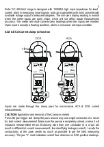
Page 6: ...t condition ACA DCA Current clamp on function Inputs are made through the clamp jaws for non invasive ACA DCA current measurements CAUTION Application and removal of the Clamp on meter Press the jaw trigger and clamp the jaws around only one single conductor of a circuit for load current measurement Make sure the jaws are completely closed or else it will introduce measurement errors Enclosing mor...

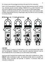
Page 7: ...Keep the jaws away from them as much as possible to minimize influence Ω Ω Ω Ω Resistance and Continuity functions CAUTION Using Resistance Continuity or Diode function in a live circuit will produce false results and may damage the instrument In many cases the suspected component must be disconnected from the circuit to obtain an accurate measurement reading Inputs are made through the test leads...

Page 8: ...verse biased across the diode The digital display shows OL if the diode is good Any other readings indicate the diode is resistive or shorted defective Capacitance function Inputs are made through the test leads terminals Slide switch on defaults at Ω Press SELECT button momentarily 3 times to select Capacitance function Relative zero mode can be used to zero out the parasitic capacitance of the l...

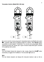
Page 9: ...ly to select degree F Fahrenheit You can also use a plug adapter Bkb32 Optional purchase with banana pins to type K socket to adapt other type K standard mini plug temperature probes HOLD The Hold feature freezes the display for later viewing Press the HOLD button momentarily to toggle to the Hold feature The annunciator turns on MAX The max feature compares and displays the measured maximum value...

Page 10: ...r to sleep mode automatically after approximately 30 minutes of neither slide switch nor push button operations to extend battery life To wake up the meter from APO press any push button momentarily or set the slide switch to the OFF position and then slide back on again Always set the slide switch to the OFF position manually when the meter is not in use 5 MAINTENANCE WARNING To avoid electrical ...

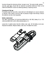
Page 11: ...e with a damp cloth and mild detergent do not use abrasives or solvents If the meter is not to be used for periods of longer than 60 days remove the batteries and store them separately Battery replacement The meter uses standard 1 5V AAA Size NEDA 24G or IEC R03 battery X 2 or 1 5V AAA Size NEDA 24A or IEC LR03 alkaline battery X 2 Loosen the 2 captive screws from the battery cover case Lift the b...

Page 12: ...61010 2 032 04 Category III 600 Volts ac dc Transient protection 6 5kV 1 2 50µs surge for all models Pollution degree 2 E M C Meets EN61326 1 2006 EN55022 EN61000 3 2 EN61000 3 3 EN61000 4 2 EN61000 4 3 EN61000 4 4 EN61000 4 5 EN61000 4 6 EN61000 4 8 EN61000 4 11 In an RF field of 3V m Capacitance function is not specified Other function ranges Total Accuracy Specified Accuracy 50igits Performance...

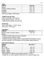
Page 13: ... to 100 of range or otherwise specified Maximum Crest Factor are as specified below and with frequency spectrums besides fundamentals fall within the meter specified AC bandwidth for non sinusoidal waveforms Fundamentals are specified at 50Hz and 60Hz DC Voltage RANGE Accuracy 400 0 mV 0 3 3d 4 000V 40 00V 400 0V 0 5 3d 600V 1 0 4d Input Impedance 10MΩ 30pF nominal 1000MΩ for 400 0mV range AC Volt...

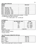
Page 14: ...500 0nF 5 000µF 50 00µF 500 0µF 3000µF 3 5 6d 1 Additional 50 00nF range accuracy is not specified 2 Accuracies with film capacitor or better 3 Specified with battery voltage above 2 8V approximately half full battery Accuracy decreases gradually to 12 at low battery warning voltage of approximately 2 4V DCA Current Clamp on RANGE Accuracy1 2 400 0A 0A 50 0A 1 0 4d 50 0A 200 0A 1 5 5d 200 0A 300 0...

Page 15: ...2 065 Crest Factor 1 8 1 at full scale 3 6 1 at half scale Hz Frequency Function Sensitivity Sine wave Range 400 0mV 350mV 10Hz 1kHz 4 000V 3 2V 5Hz 20kHz 40 00V 25V 5Hz 100kHz 400 0V 100V 5Hz 100kHz 600V 410V 5Hz 5kHz DCA ACA Unspecified Display counts 5000 Maximum resolution 0 001Hz Accuracy 0 5 4d Type K Temperature Model 063 065 only RANGE Accuracy 20 oC 300 oC 2 0 3d 300 oC 537 oC 3 0 3d 4 oF...

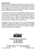
Page 16: ...prepaid to BRYMEN TECHNOLOGY CORPORATION BRYMEN assumes no risk for damage in transit BRYMEN will at its option repair or replace the defective product free of charge However if BRYMEN determines that the failure was caused by misused altered neglected or damaged by accident or abnormal conditions of operation or handling you will be billed for the repair THIS WARRANTY IS EXCLUSIVE AND IS IN LIEU ...

Reviews: