background image


1) SAFETY 

This manual contains information and warnings that must be followed for operating the 
meter safely and maintaining the meter in a safe operating condition. If the  meter is 

used  in  a  manner  not  specified  by  the  manufacturer,  the  protection  provided  by  the 
meter may be impaired. 

 
Observe proper safety precautions when working with voltages above 30 Vrms, 42.4 

Vpeak or 60 VDC. These voltage levels pose a potential shock hazard to the user. Do 
not expose this product to rain or moisture. The meter is intended only for indoor use. 

 
Keep  your  hands/fingers  behind  the  hand/finger  barriers  (of  the  meter  and  the  test 

probe assembly, where applicable) that indicate the limits of safe access of the hand-
held  parts  during  measurements.  Inspect  lead  wires,  connectors,  and  probes  for 

damaged  insulation  or  exposed  metal  periodically.  If  any  defects  are  found,  replace 
them immediately. Only use the test probe assembly provided with the meter or a UL 

Listed test probe assembly to the same meter ratings or better. 
 

Optional  offer  premium  test  probe  assembly  using  silicone  lead  wire  insulation,  at 

agent’s 

discretion,  is  equipped  with  white  inner  insulation  layers  as  wear  indicators. 

Replace them


immediately if any of the white layers has become visible. 


Disconnect the test leads from the test points before changing functions. 


The meter meets IEC/EN/CSA_C22.2_No./UL standards of 61010-1 Ed. 3.0,


61010-2-

030 Ed. 1.0, 61010-2-033 Ed. 1.0 to Measurement Categories CAT III 1000V and CAT 
IV 600V ac & dc. 

 
The accompanied test probe assembly meets  IEC/EN/CSA_C22.2_No./UL standards 

of  61010-031  Ed.  2.0  to  the  same  meter  ratings  or  better.  The  61010-031  requires 
exposed conductive test probe tips to be 

 4mm for CAT III & CAT IV ratings. Refer to 

the category markings on your probe assemblies as well as on the add-on accessories 
(like detachable Caps or Alligator Clips), if any, for applicable rating changes. 


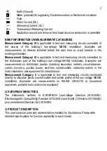
INTERNATIONAL SYMBOLS 


Marking of Electrical and Electronic Equipment (EEE). Do not dispose of this 

product as unsorted municipal waste. Contact a qualified recycler 


Refer to the explanation in this Manual 


Possibility of electric shock 

Summary of Contents for BM785

Page 1: ...USER S MANUAL BM789 BM786 BM785 Digital Multimeter ...

Page 2: ...robe assembly to the same meter ratings or better Optional offer premium test probe assembly using silicone lead wire insulation at agent s discretion is equipped with white inner insulation layers as wear indicators Replace them immediately if any of the white layers has become visible Disconnect the test leads from the test points before changing functions The meter meets IEC EN CSA_C22 2_No UL ...

Page 3: ...tion Examples are measurements on distribution boards including secondary meters circuit breakers cables bus bars junction boxes switches socket outlets stationary motors in the fixed installation and equipment for industrial use Measurement Category II is applicable to test and measuring circuits connected directly to utilization points socket outlets and similar points of the low voltage MAINS i...

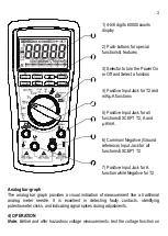
Page 4: ... Negative Ground reference Input Jack for all functions EXCEPT T2 7 Positive Input Jack for A function while Negative for T2 Analog bar graph The analog bar graph provides a visual indication of measurement like a traditional analog meter needle It is excellent in detecting faulty contacts identifying potentiometer clicks and indicating signal spikes during adjustments 4 OPERATION Note Before and ...

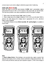
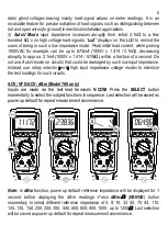
Page 5: ...he meter displays Auto when it is ready When a signal above the voltage threshold of 1V DC or AC up to the rated 1000V is present the meter displays the voltage value in appropriate DC or AC whichever larger in peak magnitude Push button features of only HOLD AutoHold EF and Backlight are available in AutoV mode Note 1 Ghost voltage Buster Ghost voltages are unwanted stray signals coupled from adj...

Page 6: ...of a second Do not use AutoV mode on circuits that could be damaged by such low input impedance Instead use rotary selector or high input impedance voltage modes to minimize the test loadings for such circuits ACV VFD ACV dBm Model 789 only Inputs are made via the test lead terminals V COM Press the SELECT button momentarily to select the subject functions in sequence Last selection will be saved ...

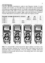
Page 7: ...er Levels see table below in sequence Press the Hz button for one second or more to leave Line Frequency function TRIGGER ACV dBm DCV AC DCV VFD ACV A mA A LEVEL 0 6V 600 A 60mA 6A LEVEL 1 60V 6000 A 600mA 10A LEVEL 2 600V 600V LEVEL 3 1000V 1000V Note It is recommended to direct measure the signals voltage or current in auto ranging mode before activating the Hz function right in that range to ge...

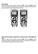
Page 8: ...ion will be saved as power up default for repeat measurement convenience DCmV ACmV DC ACmV Logic level Hz Logic level Duty dBm Model 789 only Inputs are made via the test lead terminals V COM Press the SELECT button momentarily to select the subject functions in sequence Last selection will be saved as power up default for repeat measurement convenience ...

Page 9: ... 1 second before displaying the dBm readings Press dBm RANGE button momentary to select different reference impedance of 4 8 16 32 50 75 93 110 125 135 150 200 250 300 500 600 800 900 1000 up to 1200 Last selection will be saved as power up default for repeat measurement convenience ...

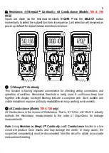
Page 10: ...ontinuous beep tone together with display backlight flashing indicate a complete wire Such audible and visible indications improve continuity readabilities in noisy working environments nS Conductance Models 789 786 only nS Conductance is the inverse of Resistance That is S 1 or nS 1 G It virtually extends the Resistance measurements to the order of Giga Ohms for leakage measurements Note Using Re...

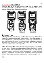
Page 11: ...open diode defective Reverse the test leads connections reverse biased across the diode The digital display shows over range if the diode is good Any other readings indicate the diode is resistive or shorted defective Beep Alert BeepLitTM indication When the display reading drops across 0 850V the meter alerts a short beep to signal a reasonable forward voltage drop of common diodes However if the...

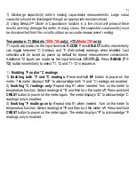
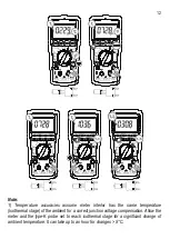
Page 12: ...urement convenience Additional T2 inputs are made via the input terminals Press RANGE T1 T2 button momentarily to select T1 T2 and T1 T2 in sequence Enabling F and or C readings 1 Enabling both F and C readings Press and hold EF button to power on the meter The meter displays C F to acknowledge both F and C readings are enabled 2 Enabling C readings only Repeat step 1 when needed Turn on the meter...

Page 13: ...has the same temperature isothermal stage of the ambient for a correct junction voltage compensation Allow the meter and the type K probe set to reach isothermal stage for a significant change of ambient temperature It can take up to an hour for changes 5 C ...

Page 14: ...na pins to type K socket adapter Bkb32 Optional purchase can be used to adapt other type K probes with standard miniature plugs However the adapter becomes part of the measurement isothermal block when in use and should be included in the overall isothermal considerations to minimize erratic readings ...

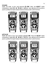
Page 15: ...lection will be saved as power up default for repeat measurement convenience of all current functions µA Current Inputs are made via the input terminals COM Press the SELECT button momentarily to select DC AC DC AC in sequence Last selection will be saved as power up default for repeat measurement convenience of all current functions ...

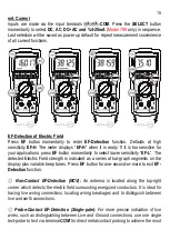
Page 16: ...sitivity EF L The detected Electric Field strength is indicated as a series of bar graph segments on the display plus variable beep tones Press EF button for one second or more to exit EF Detection function Non Contact EF Detection NCV An antenna is located along the top right corner which detects the electric field surrounding energized conductors It is ideal for tracing live wiring connections l...

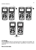
Page 17: ...tions LCD Backlight Press the SELECT button for one second or more to toggle the LCD backlight The LCD backlight goes off automatically after idling for approximately 16 minutes to extend battery life Manual or Auto ranging ...

Page 18: ...oZ AutoV VFD Volts Voltage and Current functions Significant measurements readings are 5 of range in Voltage and Current functions or non OL in Resistance function Stable reading is a significant measurement reading having 30 counts in difference with its two immediate preceding measurement readings Significant measurement readings are being displayed in real time Real Read is being displayed whil...

Page 19: ...ve mode CREST mode Press CREST button momentarily to activate CREST mode Instantaneous PEAK HOLD to capture current or voltage peak values in duration as short as 0 25ms LCD MAX turn on The meter beeps when new MAX maximum or MIN minimum reading is updated Press the button momentarily to toggle the MAX and MIN readings Press the button for one second or more to exit this mode Auto Power Off is dis...

Page 20: ...ve button while powering on the meter can shorten the APO idling time to approximately 8 seconds temporarily during the power on session It is designed mainly for production inspection Disabling Enabling oC or oF function availability See Temperature measurement operation description for details 5 MAINTENANCE Note To avoid electrical shock disconnect the meter from any circuit remove the test lead...

Page 21: ... fasten the screws Fuse use and replacement The Meter uses Fuse F1 for A input Bussmann DMM 11AR 11A 1000Vac Vdc IR 20kA F fuse Dimension 10 x 38 mm Fuse F2 for µA mA input SIBA 7017240 0 4A 1000Vac Vdc IR 30kA F fuse Dimension 6 x 32 mm Turn the rotary knob to OFF position Loosen 6 captive screws 2 are under the tilt stand from the bottom housing Lift the battery compartment cartridge Further loo...

Page 22: ...21 ...
Page 23: ... EN 61010 2 033 Ed 1 0 IEC UL EN 61010 031 Ed 2 0 and the corresponding CAN CSA C22 2 regulations to Measurement Categories III 1000V AC DC and Category IV 600V AC DC Overload Protections A mA 0 4A 1000V DC AC IR 30kA or better F fuse A 11A 1000V DC AC IR 20kA or better F fuse V 1100V DC AC rms mV Others 1000 V DC AC rms Transient protection 8kV 1 2 50 s surge E M C Meets EN61326 1 2013 Power Supp...

Page 24: ...ponents fall within the specified frequency bandwidth for non sinusoidal waveforms DC Voltage Model 789 Models 786 785 RANGE Accuracy 600 00mV 6 0000V 60 000V 0 03 2d 0 03 2d 600 00V 0 05 5d 0 05 5d 1000 0V 0 15 5d 0 15 5d Input Impedance 10M 75pF nominal 280pF nominal for 600mV range AC Voltage Model 789 1 Models 786 785 RANGE Accuracy 50Hz 60Hz 600 00mV 6 0000V 60 000V 600 00V 1000 0V 0 5 30d 0 ...

Page 25: ...00V 60 000V 600 00V 1000 0V 1 2 40d 1 4 40d 1kHz 7kHz 600 00mV 6 0000V 60 000V 600 00V 2 0 50d 2 2 50d 1000 0V Unspec d Unspec d 7kHz 20kHz 600 00mV 6 0000V 60 000V 600 00V 2 2 5 70d Unspec d 1000 0V Unspec d 1 Accuracy specified from 10 to 100 of range 2 Bandwidth specified to 10kHz only for 600V range Input Impedance 10M 75pF nominal 140pF nominal for 600mV range Residual reading less than 50 di...

Page 26: ... 1 Accuracy specified from 10 to 100 of range LoZ Auto ACV Threshold 1 0VAC 50 60Hz nominal LoZ Auto ACV Input Impedance Initially approx 2 1k 140pF nominal Impedance increases abruptly within a fraction of a second as display voltage is above 50V typical Ended up impedances vs display voltages typically are 12k 100V 90k 300V 300k 600V 670k 1000V dBm Model 789 only Range and accuracy are subject t...

Page 27: ...TM Continuity Tester Audible threshold between 100 and 420 Response time 100 s Audible Indication Beep Sound Visible Response LCD Backlight BeepLitTM Diode Tester RANGE Accuracy Test Current Typical Open Circuit Voltage 3 0000V 1 20d 0 35mA 3 1 VDC Short Beep Alert Threshold Drop Across 0 850V BeepLit continuous ON Threshold 0 100V Audible Indication Beep Sound Visible Indication LCD Backlight Cap...

Page 28: ...voltage OCV of Current loop under test at 100 V 2 The meter shows a few negative residue counts when the input is short circuited with OCV at zero volt It is the nature of the internal protection circuity design and will not affect measurement readings at nominal OCVs greater than 100 V in significant measurements 3 10A continuous up to ambient 40oC only and is 3 mins on per 15 mins off 40oC 55oC ...

Page 29: ...A 2 30mV A 1 Accuracy unspecified 10 of range 2 10A continuous up to ambient 40oC only and is 3 mins on per 15 mins off 40oC 55oC 10A to 20A for 30 seconds on per 15 mins off DC Loop Current 4 20mA Model 789 only 4mA 0 zero 20mA 100 span Resolution 0 01 Accuracy 25d Temperature Models 789 786 only RANGE Accuracy 1 2 200 0 C to 1090 C 1 0 1 0 C 328 0 F to 1994 F 1 0 1 8 F 1 Accuracies assume meter ...

Page 30: ...Sensitivity 3 0Vp square wave 2 Specified with Pulse Width 0 5 s Duty Cycle 5V Logic Frequency RANGE Specified Accuracy 5Hz 1kHz 0 10 99 99 3d kHz 2d 1kHz 10kHz 1 00 99 00 10kHz 500kHz 20 00 80 00 Sensitivity 3 0Vp square wave Non Contact EF Detection NCV Bar Graph Indication EF H Hi Sensitivity EF L Lo Sensitivity Typical Voltage Tolerance 25V 18V 45V 60V 50V 140V 50V 30V 80V 120V 100V 260V 80V 7...

Page 31: ...Amps Signal Duration REC Nominal Update Rate per Second DC 30d 300ms 10 AC 300d 80d 2 3 460ms 5 10 3 VFD 180d 800ms 5 DC AC 300d 2 2s 1 nS 1 Cx Subject to Cx Values Hz T1 T2 2 Ω T1 T2 Others 5 1 Specified at Range Locked Manual ranging 2 Specified at AC Inputs 15 of Range for Model 789 3 For Model 789 only CREST mode Instantaneous Peak Hold Accuracy Specified accuracy 100 digits for changes 0 35ms...

Page 32: ...nce prepaid to BRYMEN TECHNOLOGY CORPORATION BRYMEN assumes no risk for damage in transit BRYMEN will at its option repair or replace the defective product free of charge However if BRYMEN determines that the failure was caused by misused altered neglected or damaged by accident or abnormal conditions of operation or handling you will be billed for the repair THIS WARRANTY IS EXCLUSIVE AND IS IN L...

Reviews: