background image


18 

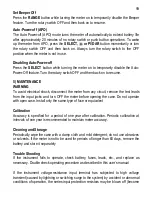
Smooth 

 mode (Insulation Resistance function only) 

Smooth 

 mode  displays  the  running  average  of  the  last  eight  measured  readings 

having  changes  within  300  counts  in  sequence.  On  the  contrary,  it  displays 
directly ,without smoothing, the measured reading that is beyond 300 counts in changes 
comparing  to  its  former  one.  Press  the 

 button  momentarily  to  enable  with  LCD 

annuciator “

” turned on. Press momentarily again to disable. 

 
Backlighted display 
 For  Model  878,  press  the 

   button  momentarily  to  toggle  the  LCD  backlight.  For 

Models  877  &  876,  press 

SELECT  button  for  a  second  or  more  to  toggle  the  LCD 

backlight.  The  backlight  will  also  be  turned  off  automatically  after  approximate  37 
seconds to extend battery life. 
 
Auto- or Manual-ranging (Volts, mA & Ω functions only)  
 Press  the 

RANGE  button  momentarily  to  select  manual-ranging,  and  the  meter  will 

remain in the range it was in, the LCD 

 turns off. Press the button momentarily 

again to select an adjacent range. Press and hold the button for 1 second or more to 
resume auto-ranging. 
 
Hold 
 The hold feature freezes the display for later view. Press the 

HOLD button momentarily 

to  toggle  the  hold  feature.  This  feature  does  not  apply  to  Earth  Continuity  Test  & 
Insulation Resistance functions. 
 
MAX/MIN Recording mode 
Press 

REC button momentarily to activate MAX/MIN recording mode. The LCD “R” & 

MAX MIN turn on. The meter beeps when a new MAX (maximum) or MIN (minimum) 

reading is updated. Press the button momentarily to read the Real-time, MAX and MIN 
readings in sequence. Press the button for 1 second or more to exit MAX/MIN recording 
mode. When activated, Auto-Power-Off is disabled automatically. This feature does not 
apply to Earth Continuity Test & Insulation Resistance functions. 
 
Beep-Jack™ Input Warning 
The meter beeps as well as displays “

InEr” to warn the user against possible damage to 

the meter due to improper connections to the “

mA” (“

 mA” for Model 878) input 

jack when other functions, especially voltage function, is selected. 


Summary of Contents for BM876

Page 1: ...USER S MANUAL BM878 BM877 BM876 Insulation Tester Combination Multimeter ...

Page 2: ... circuit breaker in the building installation Measurement Category III is applicable to test and measuring circuits connected to the distribution part of the building s low voltage MAINS installation Examples are measurements on distribution boards including secondary meters circuit breakers wiring including cables bus bars junction boxes switches socket outlets in the fixed installation and equip...

Page 3: ...finger guards of the test leads during measurement Inspect test leads connectors and probes for damaged insulation or exposed metal before using the instrument If any defects are found replace them immediately Never attempt a voltage measurement with the test lead inserted into the mA or input jack that is available Only replace the blown fuse with the proper rating as specified in this manual Onl...

Page 4: ...s identifying potentiometer clicks and indicating signal spikes during adjustments 1 3 5 6 digits 6000 counts dual displays 2 Push buttons for special functions features 3 Selector to turn the Power On or Off and Select a function 4 Input Jack for Earth Continuity Test function 5 Common Ground reference Input Jack for all functions EXCEPT Insulation Resistance function 6 Input Jack for all functio...

Page 5: ...momentarily to toggle the subject functions Last selection will be saved as power up default for repeat measurement convenience For ACV Hz function press the RANGE button momentarily to select other ranges when needed For VFD ACV Hz function only 600V range is available to best cope with the range of most Variable Frequency Drives VFD measurements To select DCV function turn the Rotary Knob to DCV...

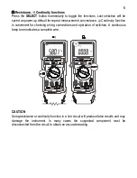
Page 6: ...ence Continuity function is convenient for checking wiring connections and operation of switches A continuous beep tone indicates a complete wire CAUTION Using resistance or continuity function in a live circuit will produce false results and may damage the instrument In many cases the suspected component must be disconnected from the circuit to obtain an accurate reading ...

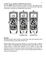
Page 7: ...nt Large value capacitors should be discharged through an appropriate resistance load Normal forward voltage drop forward biased for a good silicon diode is between 0 400V to 0 900V A reading higher than that indicates a leaky diode defective A zero reading indicates a shorted diode defective An OL indicates an open diode defective Reverse the test leads connections reverse biased across the diode...

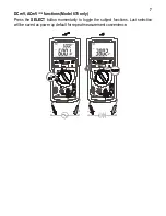
Page 8: ...7 DCmV ACmV Hz functions Model 878 only Press the SELECT button momentarily to toggle the subject functions Last selection will be saved as power up default for repeat measurement convenience ...

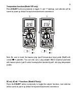
Page 9: ...banana plug type K temperature bead probe Bkp60 with correct polarities You can also use a plug adapter Bkb32 Optional purchase with banana pins to type K socket to adapt other standard type K mini plug temperature probes DCmA ACmA Hz functions Model 878 only Press the SELECT button momentarily to toggle the subject functions Last selection will be saved as power up default for repeat measurement ...

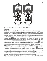
Page 10: ...n the Remote Probe Check the fuse before each If the fuse is open the meter will display OPEn when the is being activated at no circuit connection to the probes Refer to the maintenance section for fuse replacement is inhibited when the meter beeps and displays 2V plus warning against energized circuit of more than 2V is being connected before the is active Connecting to energized circuits when th...

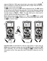
Page 11: ...dicated on the secondary display as 200mA or 90mA The meter further gives a beep sound for continuity when the active Resistance reading is 2Ω Default startup primary display reading is Allow enough time for a good measuring result After the is released the last measuring display stays until the next or a function change Lock Test mode is recommended for continuous measurements To apply press the ...

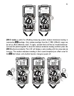
Page 12: ...eference value To apply activate the Lock Test as mentioned above Connect the probes together to show the residue resistance reading and then press the ZERO button momentarily The LCD will display a zero reading with the annuciator turns on The residue resistance reading is then saved temporarily as offset value for the that follows until a further function change or power off ...

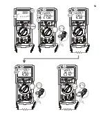
Page 13: ...all only be carried out on parts of an installation or equipment that are de energized Connecting to energized circuits when the is active will produce false results and may damage the instrument Always check with voltage functions and remove power from the circuits before carrying out the Setup as illustrated below Select an intended test voltage of 50V 100V 250V 500V or 1000V For model 878 press...

Page 14: ...xt or a function change The secondary display keeps showing the actual detected voltage readings Lock Test mode is recommended for continuous measurements To apply press the LOCK button momentarily to display the annunciator before pressing the TEST button momentarily The LCD will show both to indicate continuous measurement is active Press again either button momentarily to release the Lock Test ...

Page 15: ...14 ...

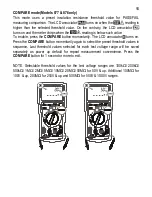
Page 16: ...he COMPARE button momentarily The LCD annuciator turns on Press the COMPARE button momentarily again to select the preset threshold values in sequence Last threshold values selected for each test voltage range will be saved separately as power up default for repeat measurement convenience Press the COMPARE button for 1 second or more to exit NOTE Selectable threshold values for the test voltage ra...

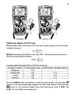
Page 17: ...eneral guide to interpret the PI or DAR test results are Insulation Condition PI Polarization Index DAR Dielectric Absorption Ratios Dangerous 1 0 Questionable 2 0 1 3 Good 4 0 1 6 Excellent 4 0 1 6 Press the PI DAR button momentarily to enable PI mode with the LCD annunciator turned on Press momentarily again toggles to the DAR mode with the LCD annunciator turned on The secondary display shows t...

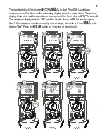
Page 18: ... down The primary display shows the real time resistance readings until the timer shows 00 00 for a result The maximum display result is 5 0 and the display shows 5 0 for results beyond that If the measured resistance reading is over range the meter will stop and display Err Press the PI DAR button for 1 second or more to exit ...

Page 19: ...urns off Press the button momentarily again to select an adjacent range Press and hold the button for 1 second or more to resume auto ranging Hold The hold feature freezes the display for later view Press the HOLD button momentarily to toggle the hold feature This feature does not apply to Earth Continuity Test Insulation Resistance functions MAX MIN Recording mode Press REC button momentarily to ...

Page 20: ...any circuit remove the test leads from the input jacks and turn OFF the meter before opening the case Do not operate with open case Install only the same type of fuse or equivalent Calibration Accuracy is specified for a period of one year after calibration Periodic calibration at intervals of one year is recommended to maintain meter accuracy Cleaning and Storage Periodically wipe the case with a...

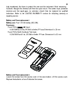
Page 21: ...ANTY section for obtaining warranty or repairing service Battery and Fuse replacement Battery use Four 1 5V AA battery IEC LR6 Fuses use Fuse F2 for mA input 0 4A 1000Vac Vdc IR 30kA or better FF fuse Dimension 6 x 32 mm Fuse F3 for Earth Continuity Test input 0 25A 1000Vac Vdc IR 30kA or better FF fuse Dimension 6 x 32 mm Battery and Fuse replacement Loosen the screws from the access cover of the...

Page 22: ... 0 IEC UL EN61010 031 Ed 1 1 and CAN CSA C22 2 No 61010 1 12 Ed 3 0 to Category III 1000 V AC DC and Category IV 600V AC DC Compliance to IEC EN61557 2007 Per CE requirements not certified by UL IEC EN61557 1 IEC EN61557 2 IEC EN61557 4 where applicable Overload Protections Insulation Resistance mA Model 878 only 0 4A 1KV IR 30kA or better Earth Continuity Test Models 878 877 only 0 25A 1KV IR 30k...

Page 23: ...Accessories Test probe pair Alligator clip pair Remote control probe Models 878 877 only Holster User s manual Bkp60 banana plug K type thermocouple Model 878 only Optional Accessories Remote control probe Model 876 only BKB32 banana plug to type K socket plug adaptor Model 878 only Special Features Record MAX MIN readings Display Hold Backlighted LCD VFD V Hz readings Lock Test mode for Insulatio...

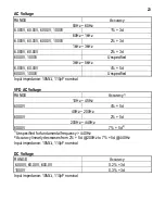
Page 24: ...00 0V 1000V Unspecified Input impedance 10M 110pF nominal VFD AC Voltage RANGE Accuracy1 10Hz 45Hz 600 0V 4 5d 45Hz 200Hz 600 0V 2 5d 200Hz 440Hz 600 0V 7 5d2 1 Unspecified for fundamental frequency 440Hz 2 Accuracy linearly decreases from 2 5d 200Hz to 7 5d 440Hz Input impedance 10M 110pF nominal DC Voltage RANGE Accuracy 6 000V 60 00V 600 0V 0 2 3d 1000V 0 3 3d Input impedance 10M 110pF nominal ...

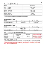
Page 25: ...cal Open Circuit Voltage 2 000V 1 5 4d 0 5mA 2 8 VDC Capacitance Model 878 only RANGE Accuracy1 3 000 F2 30 00 F 300 0 F 3000 F 1 5 5d 30 00mF 10 5d 1 Accuracies with film capacitor or better 2 Readings not available below 200nF DCmV Model 878 only RANGE Accuracy 60 00mV 0 5 3d 600 0mV 0 1 3d Input impedance 10M 140pF nominal ACmV Model 878 only RANGE Accuracy 50Hz 60Hz 1 3d 60Hz 3kHz 2 3d 60 00mV...

Page 26: ...mA 600 0mA 0 5 3d 3 0mV mA ACmA Model 878 only RANGE Accuracy Burden Voltage 50Hz 1KHz 60 00mA 600 0mA 1 5 3d 3 0mV mA Earth Continuity Test Models 878 877 only RANGE Test Current Accuracy Measuring Range1 2 000 200mA 0 015 2 199 20 00 90mA 1 5 3d 0 15 21 99 Open Circuit Voltage 4VDC Live Circuit Detector Inhibit test if terminal voltage 2V prior to initialization of test 1 Specified measuring ran...

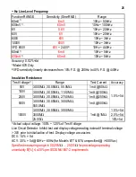
Page 27: ...rrent Accuracy 50V 3 000M 30 00M 55 0M 1mA 50k 100V 3 000M 30 00M 110 0M 1mA 100k 250V 3 000M 30 00M 275 0M 1mA 250k 500V 3 000M 30 00M 300 0M 550 0M 1mA 500k 1 5 5d 3 000M 30 00M 300 0M 1 5 5d 3000M 2 0 5d 1000V 25 0G 1mA 1M 10 5d 1 Actual output voltage 100 120 of Test Voltage Live Circuit Detector Inhibit test and display voltage reading instead if terminal voltage 30V prior to initialization o...

Page 28: ...nce prepaid to BRYMEN TECHNOLOGY CORPORATION BRYMEN assumes no risk for damage in transit BRYMEN will at its option repair or replace the defective product free of charge However if BRYMEN determines that the failure was caused by misused altered neglected or damaged by accident or abnormal conditions of operation or handling you will be billed for the repair THIS WARRANTY IS EXCLUSIVE AND IS IN L...

Reviews: