POWeR AMPLIFIeRS:
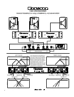
When power amplifiers of different power capabilities are used, the woofers will likely be driven by
the most powerful amplifier and the tweeters by the least powerful amplifier since the woofers can
generally be expected to be less efficient. When power amplifiers of equivalent power capabilities
are used in a bi-amped system, and when the power amps employ totally separate power supplies
for each channel (as all Bryston power amplifiers do) it is desirable to place each power amplifier as
close to its speaker as possible and use one channel to drive the woofer and the other to drive the
tweeter. Please note that if the power amps being used do not employ totally separate power supplies
for each channel, some envelope distortion between channels may occur since the power drawn from
the low frequency channel driving the woofer will usually be considerably greater than from the higher
frequency channel driving the tweeter.
POWeR AMPLIFIeR PLACeMeNT:
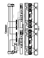
Where there is a considerable distance between the audio signal source and the speakers, it is
preferable to reduce the distance between the power amplifiers and the speakers at the expense of
increasing the distance between preamp and crossover or crossover and power amplifier. The low im
-
pedance across the speaker lines is more likely to affect signal quality with distance than is the higher
impedance across the preamp to crossover, or crossover to power amplifier cables.
BALANCeD veRSUS UNBALANCeD CABLING:
If the distance between the power amplifier and crossover or crossover and preamplifier is greater
than 30 feet, it may be desirable to use balanced cables to interconnect the two distant pieces of
equipment as this may reduce noise pickup. To facilitate this, the 10B crossover is available with bal-
anced inputs and outputs (PRO versions) using 3 pin XLR connectors (outputs use male connectors,
inputs use female connectors). Pin 3 is the positive (non-inverted or Hot) signal, pin 2 is the negative
(inverted or neutral) signal and pin 1 is ground.
Where a long run of balanced cable is used to interconnect the preamplifier to the crossover, and the
crossover is placed within a few feet of the power amplifier there is no advantage in using a balanced
interconnection between the crossover and power amplifier. Balanced cabling does not reduce noise;
it merely reduces the ability of the cable to pickup noise. The balanced output of a 10B Pro crossover
can easily be used as an unbalanced output by using XLR pin 3 (positive) as the HOT line and XLR
pin 1 as the ground line.
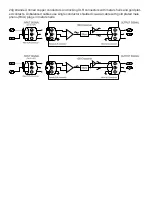
Since there is no phase inversion in the 10B, the negative XLR output pins (#2) can be used
in the same way to achieve the same effect and the output will remain un-inverted with respect to the
input. In other words, any signal that enters the negative XLR input pin (#2) will exit the negative XLR
output pin (#2) un-inverted with respect to the input. Similarly any signal that enters the positive XLR
input pin (#3) will exit the positive XLR output pin (#3) un-inverted with respect to the input. It is for
this reason that the 10B has not been changed to comply with the AES adopted XLR pin configuration
for balanced signals (pin 3 negative, pin 2 positive and pin 1 ground) and retains its original XLR pin-
out of pin 3 positive, pin 2 negative and pin 1 as ground.
Note, however, that Bryston’s current production power amplifiers do follow the AES conven
-
tion. As the above illustrations indicate, however, the 10B PRO models do not introduce any phase
inversion and thus can be used with either pin 2 hot or pin 3 hot balanced cable systems without
changing the phase relationships of the system.
CABLeS:
Bryston supplies a variety of stock audio interface cables and will supply reasonably priced semi-
custom cables (including adapter cables and cables with custom printed identification sleeves) upon
request. Bryston’s balanced cables employ double insulated, 100% shielded twisted pair cable with
Summary of Contents for 10B
Page 1: ...CROSSOVER OWNER S MANUAL for Models 10B STD 10B SUB 10B LR 1 0B ...
Page 5: ......
Page 6: ......
Page 7: ......
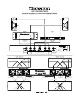
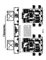
Page 8: ...CONNECTING 10B CROSSOVERS IN A STEREO 4 WAY CONFIGURATION ...
Page 9: ......


