background image

3

Art. Nr.

Item No

Abmessungen

Dimensions

Zuleitungen

Supply line

Schutzart

Protection

Belastbarkeit

Load

SV501

500 x 400 x 251 mm

2 x  seitlich

/lateral


je

/each

  Ø 25 mm,   

2 x  seitlich

/lateral


je

/each

  Ø 32 mm

IP67

Flächenlast

/area load 

max�  6,5 t

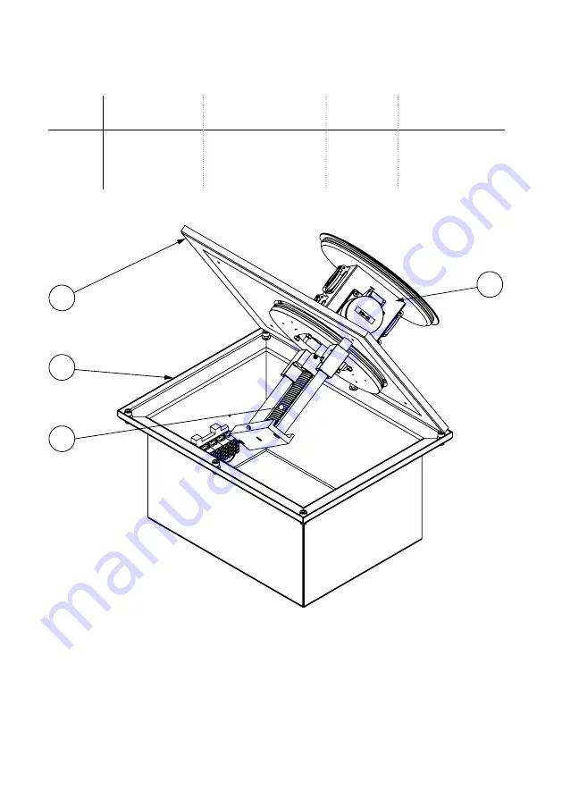
1 - Abdeckplatte

2 - Gehäuse

3 - Spindel

4 - Geräteträger Einheit

1

2

3

4

Technische Daten

/Technical specifications

Bezeichnung

/Designation:

 Abdeckplatte

/Cover plate

 Gehäuse

/Housing

 Spindel

/Spindle

 Geräteträgereinheit

/Device carrier unit

Summary of Contents for SV501

Page 1: ...Bedienungsanleitung Instruction Manual SV501 ...

Page 2: ...2 Inhalt Contents Technische Daten 3 Montageanleitung 4 Gebrauchshinweise 8 Technical data 3 Assembly instructions 4 Instructions for use 8 ...

Page 3: ...Load SV501 500x400x251mm 2x seitlich lateral je each Ø25mm 2x seitlich lateral je each Ø32mm IP67 Flächenlast area load max 6 5t t 1 2 3 4 Technische Daten Technical specifications Bezeichnung Designation Abdeckplatte Cover plate Gehäuse Housing Spindel Spindle Geräteträgereinheit Device carrier unit ...

Page 4: ...m im Kiesbett K über dem Erdreich E an der Einbauposition des Senkverteilers verlegen und mit Kies K o ä zuschütten Step 1 Unscrew device carrier unit with the cover plate from the housing Lay the drainage pipe D with a diameter of 50mm in the gravel bed K above the ground E at the installation position of the retractable supply post and fill with gravel K or similar ...

Page 5: ...asserwaage überprüfen Anschließend die Leitungen L verlegen und mit Kabelverschraubungen IP68 am Gehäuse befestigen Step 2 Pour a mortar bed M around the drainage pipe onto the compacted surface K Insert the drainage pipe into the housing from below Then place the housing on the mortar bed M Check the position of the of the retractable supply post with a spirit level before the mortar has hardened...

Page 6: ...over the mortar bed M and the cables L with it Then spread the grit SP evenly over it SP K 2 Schritt 3 Nach dem Aushärten des Mörtels M die Fläche rund um das Gehäuse mit Kies K o ä auffüllen und das Mörtelbett M sowie die Leitungen L damit bedecken Anschließend den Splitt SP gleichmäßig darüber verteilen ...

Page 7: ...ooring e g paving stones P around the retractable supply post See cross section below Schritt 4 Hiernach die Geräte anschließen und die Abdeckplatte zusammen mit der Geräte trägereinheit in das Gehäuse ein schrauben Dabei auf einen schmutzfreien Dichtungsbereich achten Abschließend den Bodenbelag z B Pflastersteine P rund um den Senkverteiler verlegen Siehe Querschnitt unten P D E SP L M S K ...

Page 8: ...f das Produkt nicht in Betrieb genommen werden Das Produkt ist unter Beachtung der nationalen Vorschriften zu entsorgen Irrtümer und technische Änderungen vorbehalten In order to ensure a lasting function of the retractable supply post the following instructions must be observed Connection repair or maintenance must be carried out by a trained specialist During installation and commissioning glove...

Page 9: ...ten Subject to errors and technical changes by BS Bodensteckdosen Systemtechnik GmbH BS Bodensteckdosen Systemtechnik GmbH Oldermanns Hof 2a 33719 Bielefeld Tel 49 521260109 90 Fax 49 521260109 99 info bodensteckdosen com www bodensteckdosen com ...

Reviews: