13
6.0
Control Operations
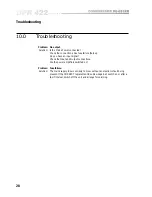
6.1 Operating Level
Control Operations
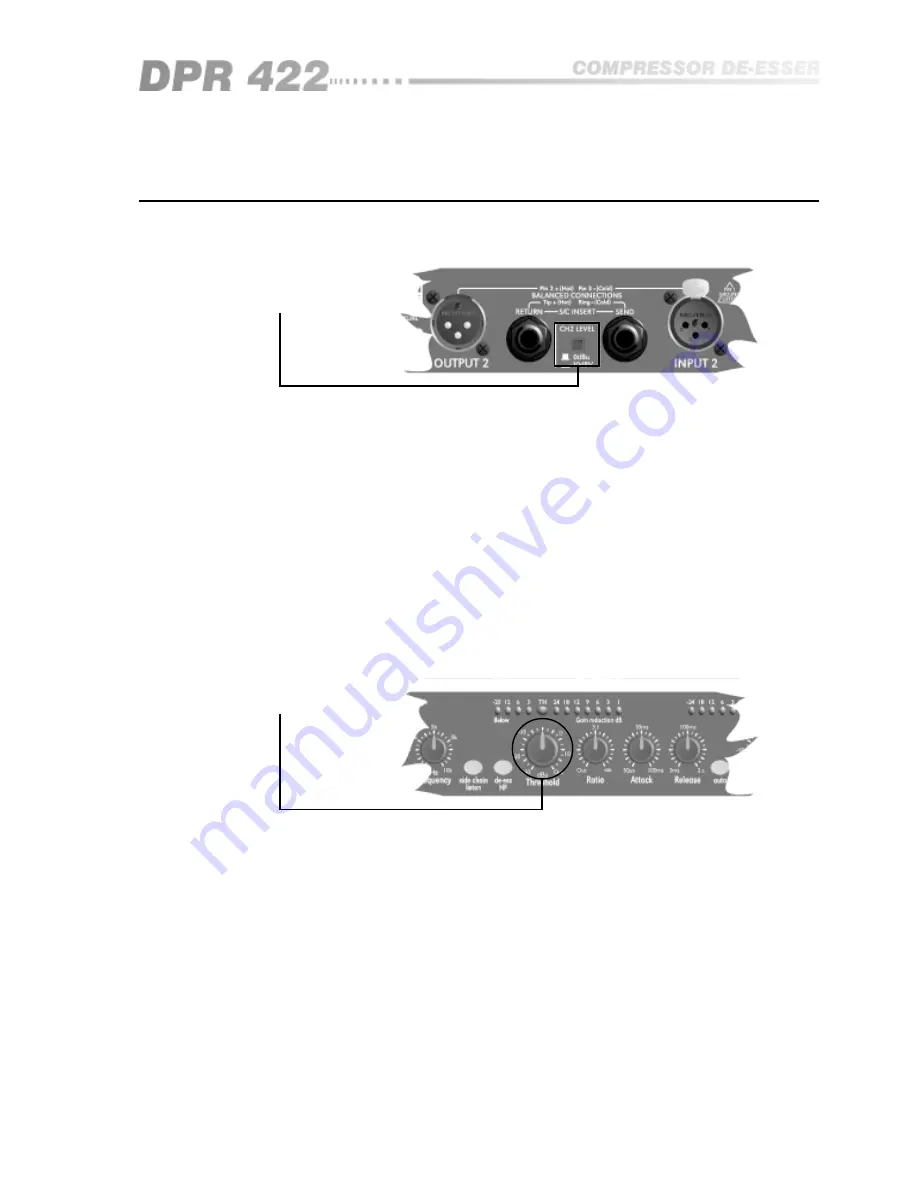
6.2 Threshold
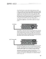
Gain reduction in the DPR-422 is achieved using a Voltage Controlled
Attenuator (VCA) with a range or operational ‘window’ of approximately 35dB.
This means that it is capable of reducing the input signal by up to 35dB or
nearly 60 times. The GAIN REDUCTION METER displays this window,
showing how much attenuation is being used. The signal level corresponding
to the lower boundary of this window is called the THRESHOLD, and input
signals below this level do not cause gain reduction. When the input level
exceeds the threshold, the gain reduction will kick in. The amount of gain
reduction or ‘compression’ produced is directly proportional to the amount by
which the input signal level exceeds the threshold.
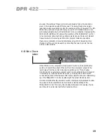
The maximum gain reduction available is set by the circuitry at a level 35dB
above the threshold. The THRESHOLD control adjusts the threshold relative to
the input signal in order to set the compressor to the required amount of gain
reduction. For example, if the average input is +12dBu and the THRESHOLD
control is set to -10dBu, then the top 22dB, [12-(-10)]=22dB, of the signal can
be compressed. The THRESHOLD control is adjustable from -30dBu to over
+20dBu.
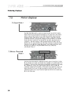
Setting this switch on the rear panel to +4dBu configures the DPR-422 for
connection in a professional system. The THRESHOLD control and OUTPUT
METER will read in dB relative to 0dBu, and the side chain insert points will be
set for connection to professional signal level equipment.
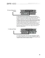
With the switch set to -10dBV, the DPR-422 shifts its internal operating point to
make it more suitable for connection to semi-professional equipment. The
internal gain structure of the unit is also optimised for these lower overall
signal levels. The insert points will also be shifted to match that of the main
signal path.
Note that in either position of the switch the DPR-422 has an overall gain of
unity (with the GAIN control set to 0dB). The insert points also have unity gain
relative to the main signal path in either mode and, of course, the operation of
the DPR-422 is the same in either mode.
Summary of Contents for DPR 422
Page 1: ...1 DPR 422 User Manual...
Page 8: ...8 The DPR 422 Fig 4 2 Rear Panel Fig 4 1 Front Panel...
Page 9: ...9 All numbers in bubbles refer to Section numbers...
Page 36: ...36 User Notes...
Page 37: ...37...
Page 38: ...38 User Notes...
Page 39: ...39...
Page 40: ...40 User Notes...


