17
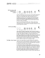
When linked, the channel 1 below threshold meter shows the combined
channel 1 & 2 signal. The channel 2 below threshold meter shows only signals
on channel 2, this provides a visual indication that there is a signal on channel
2. Note that the level on the channel 2 meter can be changed with the channel
2 threshold control, although along with the channel 2 de-ess, ratio, attack,
release and auto controls, this has no effect on the operation of the unit. If
desired, the channel 2 threshold control can be set to OUT and there will then
be no signal on the channel 2 below threshold meter. The gain reduction
meters for both channels indicate the same value, as controlled from channel
1. The output meters indicate the level on their respective channel.
If the DPR-422 is being used in either broadband or DE-ESS HF mode, it is
important that the FREQUENCY control for both channels are in the same
position.
6.8 Gain
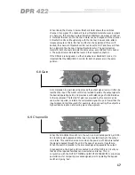
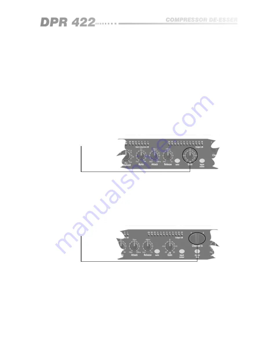
As compression is a gain reducing process, the output signal level will often be
less than the input. The GAIN control is provided to restore the output signal to
the desired operating point, and provides a calibrated range of ±20dB relative
to the input signal. The facility for gain loss provided by this control can be
used, when required, to restore the compressed signal to a point lower than the
input signal and might be useful, for example, when connecting the output to a
high sensitivity input on a following piece of equipment.
6.9 Channel In
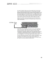
When the CHANNEL IN switch is in the out, non illuminated position, all DPR-
422 functions are bypassed and the input is connected directly to the output
via a relay. This condition also occurs when the power is off, and ensures that
the signal is passed through the unit in the case of a power or fuse failure.
When the switch is pressed in, the processed signal is passed to the output.
In bypass mode, the input is still connected to all of the DPR-422 circuitry, so
that all of the required facilities can be selected and set up. This, in
conjunction with the OUTPUT METER and INPUT METER SWITCH, provides a
powerful tool for comparing processed signals prior to operating the bypass
switch and going ‘live’.
Summary of Contents for DPR 422
Page 1: ...1 DPR 422 User Manual...
Page 8: ...8 The DPR 422 Fig 4 2 Rear Panel Fig 4 1 Front Panel...
Page 9: ...9 All numbers in bubbles refer to Section numbers...
Page 36: ...36 User Notes...
Page 37: ...37...
Page 38: ...38 User Notes...
Page 39: ...39...
Page 40: ...40 User Notes...


