15
Output Connections
10.0
Output Connections
10.2 Using XLR
Plugs
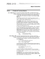
Each male XLR outputs a balanced signal - symmetrical to ground and
floating. The output is immune from short circuits and drives low impedances
and long cable runs. Each output can be interfaced directly with balanced
equipment inputs, down standard 2-core shielded terminated XLRs wired 'pin
to pin' (
As Figure 9.2
).
Pin 1: Connects to shield, screen or drain wire.
Pin 2: '-', cold or 'out of phase' output.
Pin 3: '+', hot or 'in phase' output.
If the amplifiers you are feeding have unbalanced (single ended) inputs, but
are fed from standard pin to pin XLR cables (see above), simply link the cable
at the crossover end as follows:
Pin 1: Connects to shield or screen wire.
Pin 2: Link to Pin 1.
Pin 3: Connects to the inner 'hot' or live core.
Unbalanced transmission is not recommended for connections to distant
equipment
, but is generally acceptable for local connections within the rack
or to an adjacent rack.
Technicians note:
As with a traditional transformer balanced output, either
output phase (+ or -, hot or cold) can be linked to ground to 'unbalance the
line' without upsetting the operation of the unit. As with a transformer, output
level remains the same in the unbalanced mode.
10.1 Using Phone
Plugs
Each jack socket outputs a balanced signal - symmetrical to ground and
floating. The output is immune from short circuits and drives low impedances
and long cable runs. Each socket accepts either 2-pole or 3-pole (stereo) ¼"
'A' gauge phone plugs. In general, these plugs will automatically provide a
suitable interface with unbalanced and balanced circuits respectively (
See
Figure 9.1
).
Correct phasing needs attention if the output lines are balanced. For the
majority of balanced line interfaces where the mating jack plugs tip is '+' (or
'hot' or 'in phase'), simply insert the phone plug.
If the
FDS-310
output is normally connected via jacks
but the input is
connected through an XLR plug
, be sure to check XLR polarity. If wired
according to section 8, there will be no problem. If wired with reversed
(European) polarity (Pin 2 'hot', Pin 3 'cold'), the output '+' (hot) will appear
on the phone plugs ring, not tip. In other words, the signal phase or polarity is
transposed when passing through the unit.
The situation can be resolved by swopping around the '+' and '-' connections
to Pins 3 and 2 respectively on the incoming XLR. If in doubt, use a Phase-
checker set. If
all
the surrounding XLR cables are wired Pin 2 '+' ('hot'), you
may find it more convenient to transpose the output sockets polarity. If so,
refer to section 19
. If the amplifiers you are feeding have unbalanced (single
ended) inputs, and your system is normally hooked-up with jack plugs, we
recommend you use a standard 2-pole 'A' gauge phone plug, conventionally
wired, as with a guitar lead.
Tip:
To the inner live conductor.
Sleeve:
To the cable shield or screen.
Summary of Contents for FDS 310
Page 1: ...1 FDS 310 User Manual ...
Page 10: ...1 0 Getting to know the FDS 310 Fig 6 1 Front Panel Fig 6 2 Rear Panel ...
Page 11: ...11 All numbers in bubbles refer to Section numbers ...
Page 37: ...37 User Notes ...
Page 38: ...3 8 User Notes ...
Page 39: ...39 User Notes ...
Page 40: ...4 0 User Notes ...


