2 2
Crossover Alignment Procedure
17.0
Crossover Alignment Procedure:
Setting the level controls
The modern idea is to set the crossovers' level controls so the entire speaker
system exhibits a uniform, flat response, independent of the rooms' own
acoustic anomalies. This means that powerful T.D.S. (Time-Delay
Spectrometry) equipment is needed to make speedy, reliable measurements.
When room acoustics are less than perfect and the scope for improving the
acoustics is limited, some element of compromise is needed.
A real time analyser (R.T.A.) can be used to aid setting up in conjunction with
pink noise. However, R.T.A is not the complete answer, owing to it's inability
to measure the direct sound field (it cannot altogether ignore the room's
effects). For this reason, fine tuning is always best done by ear.
Using a Real Time Analyser:
If the speaker system is concentrated in a single
stack (or several stacks), the direct sound field will generally 'come together'
about 10 to 15 feet
on axis to
(in line with the centre of) the front of the stack.
This is the optimum location for the analyser's microphone.
• With the
FDS-310
switched on and connected, make sure you have set up
the intended crossover frequency (
See sections 11.1 & 11.2
).
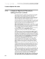
• Set all the level controls on the crossover to the 'Infinity' position (7
o'clock).
• Connect up the R.T.A. The pink noise output drives the system through the
mixer, then the crossover. For now, set the mixers output fader at 'Infinity'
(nil). All EQ controls throughout the sound system should be set to
flat
. House
EQ (if fitted) should be adjusted later, once the sound systems' basic response
has been made as smooth as possible by adjusting the crossover. The analysers
microphone is positioned on axis to the speaker stack. At this juncture, any
other speaker stacks should be muted (
See section 18
). If you are setting up a
2-Channel (stereo) system, tune up ONE channel at a time.
• Set all the power amplifiers attenuator (level) controls (where fitted) at
maximum. Alternatively, and more cautiously, you can initially set all
controls at halfway, but only if the amplifiers are identical. Otherwise the
degree of attenuation could vary widely, making it difficult to maintain
balance when the control settings are later increased to yield a better gain
structure.
• Taking the 3-way mode as an example, set the LOW RANGE control on the
crossover at 0dB, then gently raise the mixers output fader until you hear a
moderate level of pink noise rumbling through the low frequency driver(s). A
Sound Pressure Level of around 90 dB
SPL
C-weighted is optimum, being
enough to swamp the ambient noise level (unless the environment is very
noisy).
• Set the analysers sensitivity control to a suitable level, usually between 90
and 100 dB
SPL
. Then tweak the pink noise drive level using the mixers' output
fader, until the low frequency read out (typically 100Hz up to your chosen
crossover point) is averaging 0dB (referred to 90dB
SPL
) on the analysers scale.
• Now slowly turn up the MID RANGE control on the
FDS-310
until the
analyser shows the same average output level in the mid band region.
If the pink noise appears higher in pitch and/or seems to be coming from the
mid or high drive-units, turn down immediately, and re-check connections!
Summary of Contents for FDS 310
Page 1: ...1 FDS 310 User Manual ...
Page 10: ...1 0 Getting to know the FDS 310 Fig 6 1 Front Panel Fig 6 2 Rear Panel ...
Page 11: ...11 All numbers in bubbles refer to Section numbers ...
Page 37: ...37 User Notes ...
Page 38: ...3 8 User Notes ...
Page 39: ...39 User Notes ...
Page 40: ...4 0 User Notes ...

