1 6
24
0
.5
ON
OFF
.5
ON
OFF
Controls
11.0
Controls
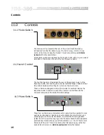
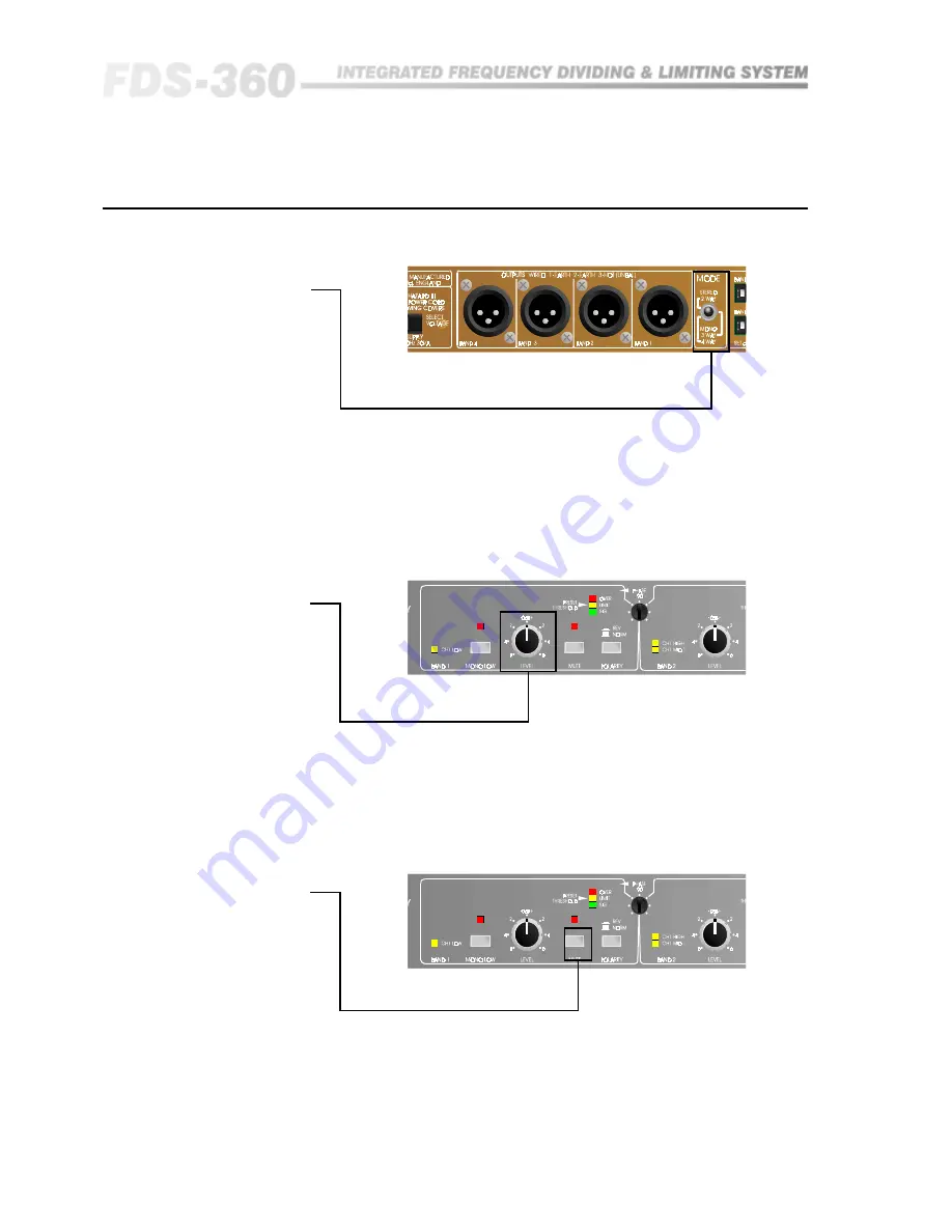
11.1 Mode Switch
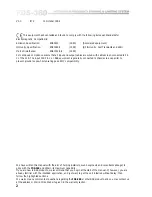
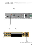
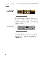
These four controls have a momentary action and allow the operator to mute
each band individually. Pressing once will activate the mute function, and
pressing again will de-mute. In addition, to protect the following speaker
system from DC power thumps, logic circuits ensure that all band outputs are
automatically muted when power is first switched on, or if a DC fault occurs
internally to the unit. This will be noted when first powering up, as the four
mute LEDs will remain on.
Refer to section 13.2
for further details.
11.3 Mute Switch
11.2 Level Control
The four front panel controls adjust the level of the program in each of the
frequency bands, and is set to give a precise restricted range of
±
6dB. In their
fully anticlockwise position they do not reduce the level to zero.
These controls are designed to allow the operator to carefully balance the
respective bands in relation to each other, and do not interfere with the
crossover networks, or the limiter threshold settings.
The mode switch is located at the rear of the unit and sets the internal
architecture for either the stereo 2-way, the mono 3-way, or mono 4-way
mode. In the mono modes, the channel 1 input connector is used.
Refer to
section 14
for other possibilities.
This selector switch also operates the front panel 'band' LEDs, to give a visual
indication of the function of each of the four frequency bands.
Summary of Contents for FDS 360
Page 1: ...1 FDS 360 User Manual...
Page 51: ...51 User Notes...
Page 52: ...52 User Notes...
Page 53: ...53...
Page 54: ...54 User Notes...

