2 2
Limiter Adjustment
15.0
Limiter Adjustment
The
FDS-360
is provided with separate limiters, each of which are carefully
designed to provide the maximum possible protection to the speaker system
by dynamically controlling the maximum power made available to the power
amplifier, and hence the loudspeakers. The frequency card has components
that optimise its response to suit the frequencies that are being controlled.
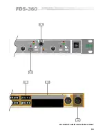
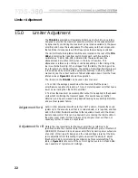
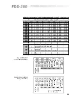
The limiter threshold adjustment switches are located on the rear of the
FDS-
360
and comprise four identical switch blocks each with five switches
calibrated as : 0.5dB, 1dB, 2dB, 4dB and 8dB. These switches act as
attenuators and are active (ON) when in the fully UP position. This
attenuation is reference to +10dBv or +4dBv depending on the linking of the
rear mounter barrier strip. When shipped from the factory the linking will be
for a threshold of +10dBv reference. The setting of individual threshold levels
is then achieved by selecting the appropriate switches in a binary addition
manner to give the correct number of dBs of attenuation down from the fixed
reference level.
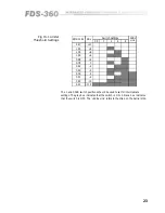
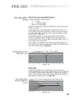
Figure 15.1
shows this operation.
The limiters on the
FDS-360
can be used in two manners:
•
To control the average power below the maximum that the power
amplifiers are capable of providing. This will protect speaker units that have a
lower power rating than that of the amplifier.
•
To allow the maximum power amplifier output to be applied to the speaker
units whilst controlling the transient peaks. This avoids heavy amplifier
distortion, and 'square waves' being applied causing heavy audible distortion
and eventual speaker failure.
Set all limiter adjustment switches to their OUT position. Operate the sound
system up to the acoustic level that is considered safe, or is required, and then
add in the limiter threshold switches to the required amount until the limiter
starts to take control. This can be observed by monitoring the middle LED on
the signal level meter. Further increase of input signal level will then not
cause any further increase in output level.
Adjustment for A
Obtain the input sensitivity for the power amplifier by referring to its
specification and then set the limiter threshold switches to give a threshold of
1dB BELOW this level. Since all power amplifiers' dynamic power output are
a function of their specific design and the mains voltage present at the time,
some adjustment from this setting might be required. The ability to adjust
threshold in 0.5dB increments gives ample scope for accurate setting. The
table in
Figure 15.1
lists some of the common signal levels in Volts and dBv
as an example of typical switch settings.
Adjustment for B
Summary of Contents for FDS 360
Page 1: ...1 FDS 360 User Manual...
Page 51: ...51 User Notes...
Page 52: ...52 User Notes...
Page 53: ...53...
Page 54: ...54 User Notes...

