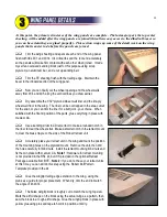
We're making progress! It will help if you have your servos and nose wheel retract on hand for some of
these subassemblies.
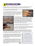
Find the coiled cable and nylon housing for the elevator and rudder
pushrods and cut them each into two pieces: 50" for the elevator and 48"
for the rudder. Lay the housings out straight somewhere out of the way,
and tape the ends so they can remain straight for a few days (or weeks).
Doing this will help relieve some of the curliness.
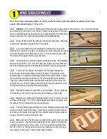
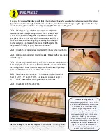
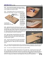
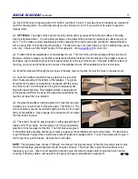
Add 4-40 blind nuts (included with the BTE retract package) to the
front of F-2 for the nose wheel retract unit. The retract should be centered
left-to-right and the top flanges should be in line with the top of F-2. Make
sure the beveled bottom edge of F-2 is facing the proper direction. Lock
the blind nuts in place with CA.
Separate the SIDE-5 pieces from
the hatch sides using a scroll saw or a
bandsaw to complete the cuts.
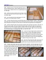
Cut apart F-3/H-3 and F-4/H-4 using the plans as a guide. Use a
knife, rather than a saw, to minimize the amount of material that is cut
away. Tape the parts back together temporarily - they will be assembled
into the fuselage as a unit.
Prepare the F-5 bulkhead by adding two F-5D doublers. Drill through
the two wing dowel holes with a 1/4" drill bit. Connect the drilled holes at
the top of F-5 to make two slots for the control cables.
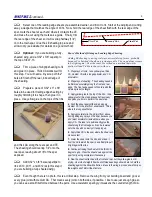
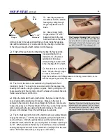
Glue the servo mount doubler to the bottom of the lite-ply servo
mount, then make a centered cutout for your elevator and rudder servos.
The overall width of the cutout should be about 2-1/4", and the distance
from the front to the rear should match your servo length plus 1/16". Add
the two balsa braces to the bottom of the mount. Position your
servos spaced apart as shown on the plans, then mark the
mounting holes, drill, and mount your servos in place using the
hardware that came with your servos.
NOTE:
Some turbine flyers
omit the rubber servo grommets, thinking there's little vibration and
it removes a possible source of linkage slop. I went that route with
the first R54, but now think using the grommets is still a good idea.
With servo arms in place on the servos, glue the entire servo
mount assembly to the front of F-5. The servo arms must be
aligned vertically with the pushrod slots at the top of the bulkhead.
Remove the servos.
Align Servo Arms
With Slots
16
F-5
F-5D
(2)
F-3
H-3
F-4
H-4
F-2
Align Parts
Upside Down
As Shown
SIDE-5
F-5
Cut
Here
Summary of Contents for Reaction 54
Page 1: ...INSTRUCTION BOOK...


