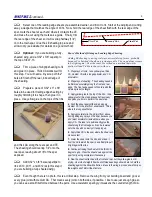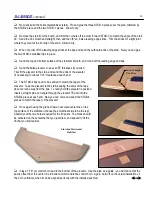
Technically, the linkages for the elevator and rudder in this design are push-pull cables, but for the sake
of simplicity, I will refer to them as pushrods. They do, after all, serve the same purpose as a rigid rod,
but their flexibility makes them easy to install. Make sure your elevator and rudder servos are in place.
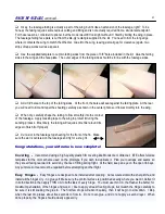
Stiffen one end of each cable by flowing solder into the first two inches. Use good soldering techniques here:
clean the cable with alcohol, apply flux, then heat until the solder flows smoothly into the cable. Allow to cool, then
clean off the flux residue with dope thinner or lacquer thinner.
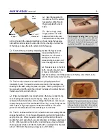
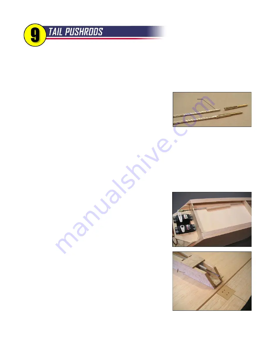
Solder a steel 4-40 threaded coupler onto each cable. You will have to
grind the soldered cable ends just slightly to make them fit into the couplers.
Heat the coupler and add more solder to the joint. When cool and clean, any
globs of solder hanging off the coupler should be ground or filed away.
Worried about the solder joint? After all, if the joint fails, your model will probably crash. I suggest you apply this
highly-scientific test. Put three or four hex nuts on the threaded coupler, clamp the nuts in a vice, grab the cable, and
give it a firm tug! If you can pull it out with your hands, you may have just saved your model. If not, you did a good job
of soldering and you can proceed without worry.
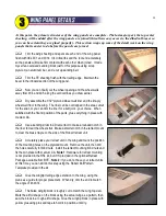
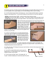
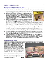
Now it's time to install the nylon housings (tubes), starting with the elevator. Before you put it in the model, swipe
the outside of the tube with sandpaper to roughen it up, then wipe it clean with alcohol. Make sure each end is cut
cleanly and the cable slides in without binding. Insert the 50" elevator cable into the 50" tube, then thread a 4-40 jam
nut and gold clevis onto the threaded coupler. Route the tube through the holes in F-5, F-6, and the hardwood clamp
at the tail. Connect the clevis to the elevator servo arm.
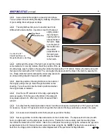
Cut a four-inch length of 5/16" square balsa to use as a guide for the
tube as shown on the plan. Notice that the end of the tube should be
positioned 3/4" behind F-5, and the end of the balsa stick is about an inch
back from the end of the tube. Get everything aligned, then glue the balsa
stick and the tube (medium CA works well) to the fuel compartment top.
Leave the front inch of the tube unglued so it is free to wiggle side-to-side
with the movement of the servo.
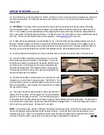
Now work your way back, gluing the tube to the fuselage side as you
go. It should pass right over the top corner of F-8. The idea is to route the
tubing as smoothly as possible back to the elevator. Glue it to the hardwood
clamp, but leave it free aft of the clamp.
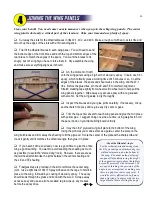
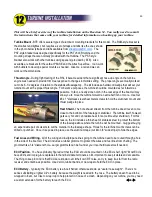
Pin the stab to the fuselage, and tape your elevator in place. You can
now establish the final position of the elevator control horn. The long arm of
the horn should be very close to the model's centerline, but you can adjust
as necessary to make sure the cable flows smoothly to the control horn. You
can trim the tubing (remove the cable first) to its proper length, but I like to
leave the cable extra long until later. Mark the mounting holes for the control
horn, drill at the marks with a 3/32" drill bit, then harden the wood around the holes with thin CA.
NOTE:
The final
solder clevis will be installed after the model is finished and the stabilizer and elevator are in their final position.
23
Grind
Summary of Contents for Reaction 54
Page 1: ...INSTRUCTION BOOK...

