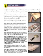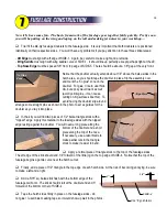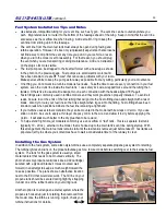
Add the fin to the top of the stab with the rudder taped in place. Temporarily tape the rudder control horn to the
rudder in the position shown on the plans (see Sheet 5). The angled orientation of the horn is required to match the
angle of the pushrod as it emerges from the stabilizer.
This might be the trickiest step in the whole building process. You need to drill a hole through the stabilizer and
stab mount at a low angle for the rudder pushrod. Use a long drill bit that is undersize, say 3/32". When viewed from
the side, the drill is obviously pointing down towards the stabilizer at an angle of about 30º. When viewed from the
top, the drill is also angled towards the center of the model.
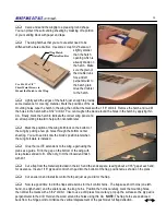
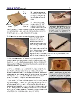
Ideally, the drill bit needs to pass directly through the outermost
hole in the rudder control horn. It's nice to have the horn in
position for reference, but it's also in the way of the drill bit. Once
you have a good idea of the drill position, you can remove the
horn or swing it out of the way while you drill. The "magic spot" for
drilling through the stab is shown in the photo.
Ultimately, this hole must be enlarged to 3/16" to fit the
pushrod housing. You can use progressively larger drills, or work
more slowly with a small file. Remove the stabilizer.
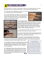
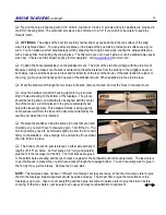
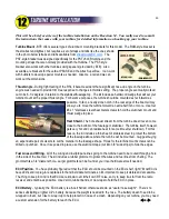
Now you can route the rudder pushrod through the holes in F-5, F-6, and the
stabilizer mount hole. Again, route the tubing as smoothly as possible and glue it
to the fuselage as you did with the elevator tube. When you get to the aft end,
carefully glue the tube to the stab mount only (not the stabilizer). Cut off the
housing flush with the top of the stab mount.
The hole in the stabilizer needs to be enlarged to a diameter of 1/4" or more
to provide clearance for the cable and solder clevis. Use a drill, file, or Dremel tool
to enlarge the hole.
Optional:
You can leave the wood bare inside the hole, or
line it with some type of large tubing (not provided in kit - I used some black plastic
tubing about 5/16" diameter).
Finally, re-install the stab and fin, and use the installed pushrod to locate the
final position of the rudder control horn. Drill holes and harden the wood in the
rudder with thin CA.
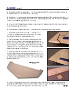
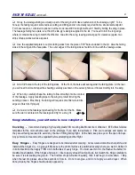
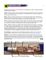
Once the tail surfaces are glued in place and the control surfaces are hinged, you can add the final solder clevis
to the ends of pushrods. Start by cutting the cables to their final lengths. Remove the cables and stiffen the last 2"
with solder as you did at the front. Grind
the ends if necessary to fit the clevises.
Re-install the cables and carefully position
the solder clevises. The clevises must be
soldered in place on the model, so protect
the surrounding area with a rag while you
solder. Make final length adjustments at
the front end of each pushrod.
R54
TAIL PUSHRODS
,
continued...
24
7/8"
1/2"
Magic Spot
Come back to this final step after control surfaces are hinged
Summary of Contents for Reaction 54
Page 1: ...INSTRUCTION BOOK...


