Fuel System Installation Tips and Notes
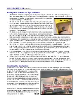
Use kerosene-compatible tubing for your vent line, such as Tygon. The vent line can be routed anywhere you
wish. My preference is to route it to the bottom of the fuselage ahead of the wing. Keep in mind that the vent line
also serves as the overflow line when fueling. Add a small O-ring to keep the
vent line from sliding up into the fuselage.
The vent line from the main fuel tank must always be open during fueling and
turbine operation. However, it's been my (unpleasant) experience that kerosene
will find a way to drip from the vent any time you put it in your vehicle, or even
when you turn the model over for assembly. For that reason, you should plug
the vent when you are transporting or doing maintenance. Add a red streamer
on the plug so it's more visible.
The fuel pump can be strapped to the boat tail former with a tie-wrap as shown
in the photo on the previous page. Fuel pumps are small electric motors and
have been known to create RF "noise" that can cause problems with your radio.
Make special efforts to keep the pump as far away as possible from any wiring, particularly your radio antenna.
One thing you do not want in a turbine model is fuel leaks. Take the time to secure every connection in your fuel
system, even the clunk line inside the main tank. I use safety lock wire, wrapped twice around the tubing then
twisted. Others like to use small tie wraps; two on each connection with the heads aligned 180º apart.
Festo fittings are commonly used in turbine models, and they work great when properly installed. To avoid air
leaks, be sure to cut the ends of the fuel tubing that will go into the Festo fitting clean and straight with a razor
blade. Also try to route your fuel line so that it is straight when it goes into the fitting. Festo fittings have been
known to leak when positioned where the fuel line is making a tight bend.
If your turbine uses external solenoids, they can be mounted to the model with tie wraps or Velcro. If you use
stick-on Velcro, be sure to apply a thin layer of epoxy or CA to the wood and allow it to dry before applying the
Velcro. It will stick much better to the dry glue than to bare wood.
To help extend flight time, jet modelers commonly use an overflow or "taxi" tank. This is a separate fuel tank
(typically 10 - 20 oz.), external to the model, that is hooked up to the main tank's vent line during startup. With
this arrangement, the main fuel tank remains full until the taxi tank is removed just before takeoff. Taxi tanks are
popular at jet fly-ins where you sometimes have to wait a considerable time for the runway to clear.
Installing the Gas System
In addition to the fuel system, some older-style turbines use a completely separate propane gas system for starting.
The turbine ignites and runs on the propane/butane gas for a few seconds before switching over to the kerosene fuel
system. The tank for the gas system is usually a small
metal canister that needs to be mounted vertically. The
photo shows my propane tank (looks like a C02 cartridge)
secured with a plywood bracket. It was mounted well
forward in an attempt to keep as much weight toward the
nose as possible. The plans show an alternative location
next to the ECU that would also work. The fill line on your
propane tank should be secured during flight by strapping
it under one of the rubber bands on your wiring rack.
Another option is to arrange an external system where the
propane is hooked up just for starting, then removed from
the model once the turbine is running. Again, check your
turbine instructions for details.
R54
FUEL SYSTEM INSTALLATION
,
continued...
29
Vent Line
Summary of Contents for Reaction 54
Page 1: ...INSTRUCTION BOOK...

