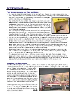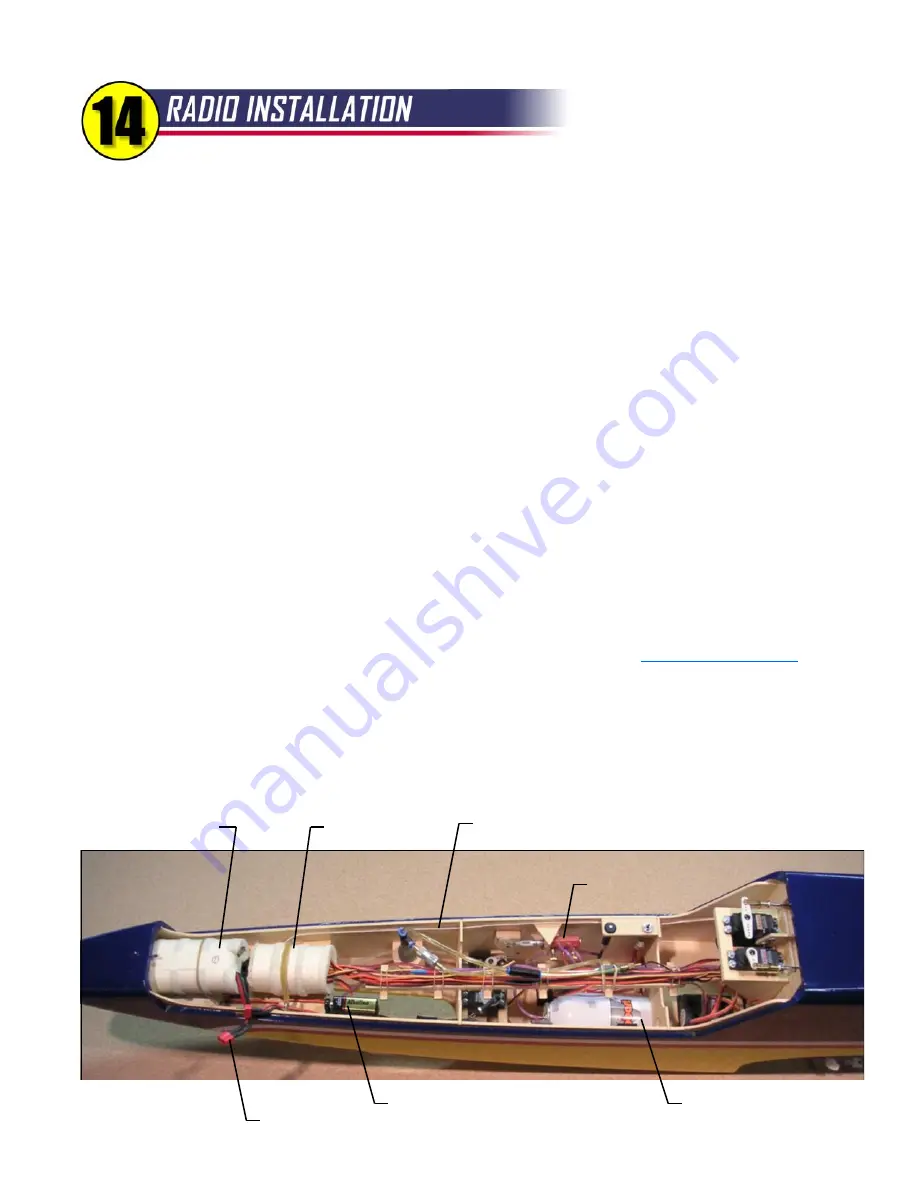
In turbine models, neatness counts! Pay attention to the details and you will be rewarded with jet that is
reliable and easy to maintain.
Receiver
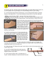
- Position the receiver in the nose to help with nose weight and to separate it from the ECU. Wrap it in foam
rubber, not for vibration protection but for crash protection. The hatch bulkhead H-2 may need to be cut away at the
bottom to make room for the receiver.
Battery
- Again, the radio battery is located in the nose for nose weight and wrapped in foam for crash protection.
Many modelers like to use two batteries for redundancy. Use high-quality components and stay on top of your battery
condition at all times. Remember, most radio failures in models of all types are battery related.
Switch
- It is important to make the switch (or switches) accessible. With it mounted to the receiver shelf, it appears to
be covered by the ECU battery, but it's still easy to access and this hasn't caused me any trouble in the field. Make
sure the switch cannot be bumped off accidentally by the battery (or anything else) shifting in flight.
Servos
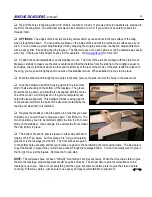
- Installation of the elevator and rudder servos was pretty well covered during construction. The wing servos
are mounted using the hardware supplied with the servos. The pushrods for the ailerons and flaps are shown in detail
on the plans. Note the position of the servo arms for each control surface. The steering and retract servos can be
mounted to basswood rails aft of F-3. Try to get the rails as low as possible in the fuselage, not only to align the
steering servo favorably with the nose wheel retract unit, but also to leave room to get the retract air tank in and out. If
you use bigger servos or mount the rails higher, you may have to put the tank in first and consider it "built in".
Servo Extensions
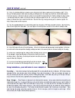
- You will need a variety of servo extensions for the R54. Don't skimp here - use high-quality,
heavy-duty leads from reputable sources. I buy all my extensions and switches from
www.electrodynam.com
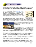
Wiring Rack
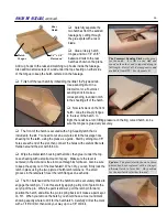
- The plans and photos show the balsa wiring rack that I developed for this model. It's a handy way to
bundle all the servo leads and air lines running back and forth in the forward fuselage. The rubber bands (included in
the kit) allow quick and easy maintenance if you ever need to change a wire or air line. The wiring rack itself is held to
small basswood blocks on F-3 and F-4 using two flat-head screws. Countersink the balsa for the screws so they won't
interfere with the wiring.
R54
ECU Battery
Receiver Battery
is under the ECU
Battery
Antenna - keep it separated from all other wiring
Receiver
9V Battery for Kavan Brake
ECU Battery Connector - disconnect between flights
Retract Valve
Retract Air Tank - wrap
with tape for snug fit in F-4
32
Summary of Contents for Reaction 54
Page 1: ...INSTRUCTION BOOK...

