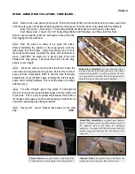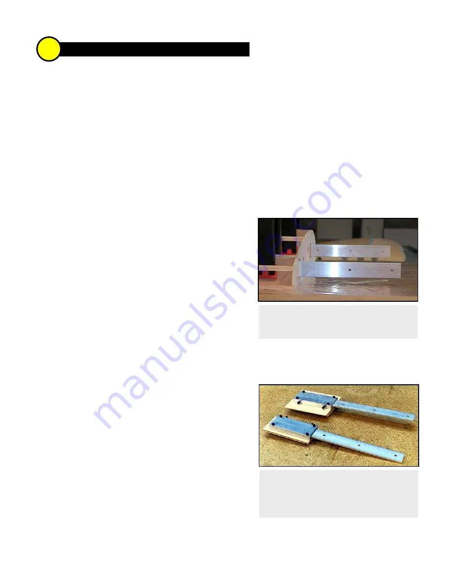
Top: Front Joiner Assembly. Bottom: Rear
Joiner Assembly -
At this point, the joiners have
been fastened to the center section shear webs.
Notice the "open" side of the C-channel is
positioned against the face of the plywood web.
With the center panel flat on the table
and the
assemblies clamped in place, make certain the
joiners are parallel to each other and the table.
1 WING JOINER INSTALLATION >
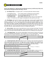
Prepare the wing joiners exactly as described in the Sig directions. Okay, maybe one exception: If you don't
have numbered drill bits (like me), you can use a 7/64" drill for the 4-40 bolts (the mounting bolts, not the set screws)
and a 9/64" drill for the 6-32 bolts. Slide the joiners into the C-channels, tighten the set screws, and set aside.
Use the Shear Web Identification drawings (on the plans) to locate the internal shear webs A, B, and C. Trial
fit these internal webs between the main spars. Trim as necessary; try for a snug fit.
Trial fit the external shear webs D, E, and F against the aft faces of the main spar. Actually, webs E and F
should fit perfectly because you used these earlier to position the W-2 ribs. Hold the webs in place and mark the
spar locations using a pencil from the front side. Now you can glue the internal webs to the external webs using the
pencil lines for proper alignment. Web A glues to web D, B glues to E, and C glues to F.
Trial fit the three rear shear webs G, H, and J against the rear spars; trim to fit as necessary.
Working with the center wing panel only, position the
shear webs for the C-channels, front and rear. No glue yet! You
might have to use tape to hold the rear web in place against the
rear spars. Now position your joiner assemblies on the webs. I
positioned my set screws heads-down, so they can be tightened
through holes in the bottom of the wing. They may be positioned
on top, if you prefer. Visually inspect the aluminum joiners to be
certain they are parallel, then mark the webs (mechanical pencil)
through the four mounting holes in each C-channel.
Remove the joiner assemblies and the webs from the
center panel, then carefully drill the webs (3/32” drill bit) at the
marks. Bolt the C-channels to the webs using the high-quality hardware supplied with the kit:
Each Front C-channel: Four 4-40 x 1" Socket-Head Bolts, #4 Washers, and 4-40 Hex Nuts
Each Rear C-channel: Four 4-40 x 3/4" Socket-Head Bolts, #4 Washers, and 4-40 Hex Nuts
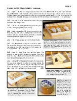
You will have to notch the rear spars to clear the
mounting hardware used on the rear joiner. Try to make the
notches as small as possible in order to maintain spar strength.
Temporarily fit the shear webs in the outer wing panel,
front and rear. Again, you may have to tape the rear webs to
the rear spars.
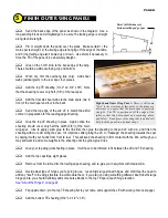
Position the webs with the joiner assemblies in the
center section, again without glue. With the center section firm
on your table (I used beanbags filled with lead shot), slide the
outer panel into position. Prop up the wingtip end of the outer
panel 1-1/4" off the table for proper dihedral. The W-2 ribs
should fit against each other pretty well at this point, and the
aluminum joiners should be resting against the faces of the plywood webs in the outer panel. Carefully mark the
webs through the joiner mounting holes.
3
PAGE 4
Summary of Contents for SUPER FLYIN' KING
Page 2: ...TABLE OF CONTENTS 0 1 2 0 3 4 5 4 4 2 22 0 2 0 0 0 6 0 7 1 0 2 2 8 9 6 7 5 2 1...
Page 22: ...0 1 2 3 4 1 5 6 7 PHOTO 1 PHOTO 2 PHOTO 3 PHOTO 4...
Page 23: ...0 1 2 3 PHOTO 1 PHOTO 2 PHOTO 3 PHOTO 4...
Page 24: ...4 5 4 6 4 0 7 0 8 0 0 9 4 1 PHOTO 5 PHOTO 6 PHOTO 7 PHOTO 8 PHOTO 9...
Page 25: ...1 0 1 9 5 9 7 6 A PHOTO 10 PHOTO 11 PHOTO 12...
Page 28: ...0 12 3 4 5 6 7 6 8 3 9 7 9...
Page 31: ......


