background image

 1    WING SUBASSEMBLIES       >  


Time for a bit of tedium here.  Once these time-consuming tasks are done, you will be ready to take on the 
final assembly of the wing panels with minimal delay.  Let's roll... 




Sort the Balsa Sheets


-

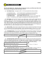
 Go through the 3/32" x 3" x 36" sheets provided and sort them as follows: 


16 Leading Edge Sheeting - 

Look for medium weight, long grained pieces that bend uniformly 


8 Center/Wing Joint Sheeting - 

This can be slightly heavier than the leading edge sheeting 


8 Trailing Edge Sheeting - 

Use the heaviest, stiffest sheets here. 


12 Aileron/Flap Sheeting - 

Light to medium wood is okay, you want to keep the control surfaces light 


2 Leftover - 

You'll need some for the Fuselage, but mainly these are extras (you know, just in case) 




Flap Sheeting

 -

 Select six 3/32" x 3" sheets to use as flap sheeting.  Cut all six sheets to a length of 24" and 

save the 12" cutoffs for later.  Take four of the 24" sheets and slice them down the middle, lengthwise.  Now you 
should have eight pieces, 1-1/2" x 24".  These will be used as the top and bottom sheeting for the flaps (two on top, 

two on bottom of each flap).  If the edges are slightly bowed, you can trim them again to a width of 1-3/8"; it's not 
critical.  Take the two remaining sheets and slice each slightly off-center so that you end up with a piece that's 1-5/8" 
and another that's 1-3/8".  The 1-5/8" x 24" strips are for the front face of the flaps and the 1-3/8" x 24" strips are for 
the rear face of the wing.  Mark the sheeting as you go so you'll remember their uses later on. 




Aileron sheeting

 -

 Select another six sheets and slice four of them in half along their full length.  These eight 

1-1/2" x 36" pieces will be used for aileron sheeting.  Cut the remaining two sheets to 1-5/8" and 1-3/8".  Like the 
flaps, the 1-5/8" x 36" strips are for the front face of the ailerons and the 1-3/8" x 36" strips are for the wing rear face. 




Trailing Edge Sheeting

 -

 These need to be trimmed slightly.  Trim four sheets to a width of 2-3/4"; these will 

be used on the top surface of the wing panels.  Trim four pieces to 2-1/2" to use on the wing bottom.  The top and 
bottom sheets for the center panel will need to be spliced.  Make the splices in all sheeting at least 8" long. 




Leading Edge Sheeting, Outer Panels

 -

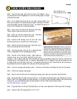
 Make four sets of LE sheeting.  Each set is made from two pieces 

of balsa, edge glued along their entire length.  The tricky part here is that the final width of the LE sheet MUST be as 
close  to  6"  as  possible,  which  means  there  is  very  little  room  for  trimming.    Fortunately,  most  sheets  are  slightly 
oversize, so it may be possible to trim them if necessary.  Try to find sheets that match without trimming. 





Leading Edge Sheeting, Center Panel

 -

 Make two sets.  This one is the trickiest.  If I can do it, so can you.  

Start with the splices, then do the long edge joint.  Again, keep the overall width as close to 6" as possible. 


PAGE 6 

8" 

3/32" x 2-3/4" x 36" Balsa Top TE Sheeting 

Not to Scale 

3/32" x 3" x 36" Balsa  - 2 Sheets Edge Glued 

Leading Edge Sheeting, Outer Panels - Make 4 

6" Preferred, 5-7/8" Minimum 

Leading Edge Sheeting, Center Panel - Make 2 

Summary of Contents for SUPER FLYIN' KING

Page 1: ...hes Wing Area 3380 square inches Length 96 inches Weight 36 pounds approximate Engine Range 60cc 80cc Gas Manufactured by BRUCE THARPE ENGINEERING 8622 E EVANS CREEK ROAD ROGUE RIVER OR 97537 phone 54...

Page 2: ...TABLE OF CONTENTS 0 1 2 0 3 4 5 4 4 2 22 0 2 0 0 0 6 0 7 1 0 2 2 8 9 6 7 5 2 1...

Page 3: ...is 2 move the web all along the rib to be sure it is straight along its entire length front to back Left Outer Wing Panel with all spars sub LE and servo lead tube in place Shear webs have yet to be...

Page 4: ...tick to hold the ends of the W 1 ribs but found out later it would have been smarter to use a sheet of 3 32 balsa maybe one or two inches wide Use only a few spots of glue so it can be removed later A...

Page 5: ...r webs for the C channels front and rear No glue yet You might have to use tape to hold the rear web in place against the rear spars Now position your joiner assemblies on the webs I positioned my set...

Page 6: ...er Three 6 32 x 3 4 Socket Head Bolts Six 6 Washers and Three 6 32 Hex Nuts Notice I used a washer under the bolt heads to keep the bolts from digging into the aluminum Now the webs are ready to be gl...

Page 7: ...ace of the wing Mark the sheeting as you go so you ll remember their uses later on Aileron sheeting Select another six sheets and slice four of them in half along their full length These eight 1 1 2 x...

Page 8: ...t to add extra wood for trimming curved corners later Center TE Sheeting no diagram This is to sheet the small wing section between the flaps in the center wing panel The final piece for the top shoul...

Page 9: ...he sub LE to match the airfoil contour in preparation for the leading edge sheeting Glue the top LE sheeting in place Again notice the sheeting should cover only half the width 3 8 of the main wing sp...

Page 10: ...build a flat wing panel once the remaining sheeting is glued in place your wing panel will be locked into its final state In case you re wondering the SFK doesn t have or need washout Try for zero wa...

Page 11: ...I had to sand nearly a full ply off to make the plate match the thickness of the balsa sheeting Check yours before gluing and take steps to be sure it will be flush with the trailing edge sheeting to...

Page 12: ...x 4 1 2 x 10 1 8 When dry flip the wing over upside down and pin it down this time with the top spar against the table Support the TE with a stick then take a long careful look at the panel from all...

Page 13: ...beveled to match the slope of the ribs Remember to make right and left ailerons and flaps Aileron Upside Down After sanding the front face of the aileron I decided that my hinges would need more mater...

Page 14: ...Drill 3 8 holes for the tail brace hard points as shown on the plans Add the dowels and the lite ply reinforcements When dry use your big sanding block to sand both sides of the stabilizer flat The el...

Page 15: ...the model s centerline so that the prop shaft ends up centered at the front of the model Cowling and Spinner This is where builders will need to do their greatest amount of innovating because of all t...

Page 16: ...n 6 0V and they are inexpensive You will need a variety of servo extension wires Y harnesses and possibly servo reversers I ve had real good luck with the products from Electrodynamics they use heavy...

Page 17: ...nition wire Carb Box as recommended by Cactus Aviation Only bottom of carb box is attached to F 1 the top and sides are removable Bottom of box has large hole for air intake Bellcrank is linked to cho...

Page 18: ...sets the tailwheel mount and the diagonal sticks on the bottom of the fuselage This picture is a little out of order because some upcoming steps are already done here The plywood plate in front of F 3...

Page 19: ...recess it into the fuselage as shown here If not the length of the rear mount will have to be trimmed The half moon cut at the front of the bottom sheet is optional it s purely for looks The big hole...

Page 20: ...o support false floors which of course I ve yet to finish Fuselage Top showing the cabin rear and laminated wing blocks glued in place Cabin Rear Wing Block Support Fuselage Top showing the position o...

Page 21: ...sheeting extends rearward slightly to overlap the front of the stabilizer Also notice that I added some balsa triangle stock to reinforce the tailwheel mount Above Hatch removed The hatch is held down...

Page 22: ...0 1 2 3 4 1 5 6 7 PHOTO 1 PHOTO 2 PHOTO 3 PHOTO 4...

Page 23: ...0 1 2 3 PHOTO 1 PHOTO 2 PHOTO 3 PHOTO 4...

Page 24: ...4 5 4 6 4 0 7 0 8 0 0 9 4 1 PHOTO 5 PHOTO 6 PHOTO 7 PHOTO 8 PHOTO 9...

Page 25: ...1 0 1 9 5 9 7 6 A PHOTO 10 PHOTO 11 PHOTO 12...

Page 26: ...ut there may be times in the future when nobody is available Of course some would argue that flying alone is unsafe too but I ll leave that up to you The eyelet is bolted to a 1 4 plywood plate and is...

Page 27: ...LERONS 1 5 8 UP 1 DOWN ELEVATOR 1 UP 1 DOWN RUDDER 1 1 2 LEFT 1 1 2 RIGHT RUDDER DEFLECTION WITH FULL AILERON 3 4 FLAP DEFLECTION FULL MOVEMENT 40 DOWN ELEVATOR WITH FULL FLAPS 7 16 0 1 2 3 0 0 4 5 6...

Page 28: ...0 12 3 4 5 6 7 6 8 3 9 7 9...

Page 29: ...ough call It might be okay without them but I didn t want to find out the hard way that I was wrong I added wires to mine which have held up well but there are sturdier and more expensive alternatives...

Page 30: ...ALL BALSA PARTS BAG 4 1 4 4 6 4 5 0 9 3 0 7 9 3 0 1 3 0 3 0 SMALL PLY HARDWOOD PARTS BAG 3 0 8 8 1 4 4 LITE PLY PARTS 3 8 7 1 2 4 3 2 4 9 2 3 9 2 4 9 2 1 2 5 9 1 2 4 2 9 2 2 6 2 2 4 9 2 0 2 6 5 2 0 2...

Page 31: ......

Reviews: