background image

RU4370 User Manual

Copyright © 2021 BTI WIRELESS All rights reserved.

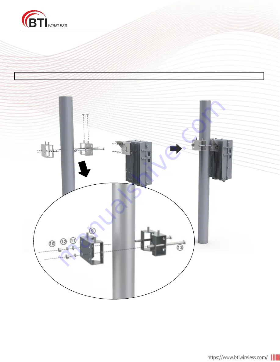
Pole Installation

1. Install the handle and Bracket I to the back of RU4370.
2. Install the bracket II and Bracket III to the pole.
3. Hang the RU4370 on the mounting bracket and fasten with nuts M10.
4. Connect the ground cable and power cable.

Note: The diameter of Pole shall not be over 110mm or less than 55mm.

Summary of Contents for RU4370

Page 1: ...RU4370 User Manual Copyright 2021 BTI WIRELESS All rights reserved RU4370 User Manual 4T4R Digital Radios High Output Power Outdoor Rated ...

Page 2: ...e liable for any loss or damage direct or consequential suffered by any party because of the contents of this publication or the reliance of any party thereon or any inaccuracy or omission therein The information in this document is therefore provided on an as is basis without warranty and is subject to change without further notice and cannot be construed as a commitment by BTI Wireless The produ...

Page 3: ...nt General 4 Warnings 4 Site Considerations 4 Environmental 4 Warning Marks 6 Preparation 8 Unpacking and Inspection 8 Tools 8 Installation of the RU4370 9 RU4370 Accessories 9 Wall Installation Back on the Wall 10 Wall Installation Side on the Wall 15 Pole Installation 19 ...

Page 4: ...the equipment off and on the user is encouraged to try to correct the interference by one or more of the following measures Reorient or relocate the receiving antenna Increase the separation between the equipment and receiver Connect the equipment into an outlet on a circuit different from that to which the receiver is connected Consult the dealer or an experienced radio TV technician for help Not...

Page 5: ...RU4370 User Manual Copyright 2021 BTI WIRELESS All rights reserved Maximum humidity 100 Temperature range 40 to 55 ...

Page 6: ...s on the equipment shell should be kept clean readable and identifiable ALWAYS disconnect all lines and power connections before servicing or disassembling this equipment NEVER touch the surface after the devices power on For performance and safety reasons NEVER disassemble and remodel the devices ...

Page 7: ...RU4370 User Manual Copyright 2021 BTI WIRELESS All rights reserved ...

Page 8: ...e that all equipment and accessories have been delivered 3 Ensure that all equipment and accessories have no damage If there is any damage contact your BTI service agent Tools Electric drill cross head screwdriver side cutters ladder and other tools are needed for RU4370 installation which is not offered from BTI for now Customers to provide these tools themselves Drilling Machine Pen Allen Wrench...

Page 9: ...RU4370 User Manual Copyright 2021 BTI WIRELESS All rights reserved Installation of the RU4370 RU4370 Accessories Figure 1 RU4370 Accessories ...

Page 10: ...WIRELESS All rights reserved Wall Installation Back on the Wall 1 Attach and fasten the handle to the side of RU4370 with screws M6 14 using T5 Wrench 2 Attach and fasten the Bracket I to the back of RU4370 with screws M6 14 using T5 Wrench ...

Page 11: ...RU4370 User Manual Copyright 2021 BTI WIRELESS All rights reserved 3 Mark the position of the drilling holes in the mounting Bracket II Note R 13mm 4 Drill 4 holes at the marked positions Note H 70mm ...

Page 12: ...Attach the dowels expansion screws or the like and fasten the Bracket II to the wall Tips use Bracket II as a reference to control each devices separation distance before hanging and locking RU4370 up 6 Hang the RU4370 on the mounting bracket II and fasten with nuts M10 ...

Page 13: ...RU4370 User Manual Copyright 2021 BTI WIRELESS All rights reserved 7 Fasten the Bracket I and II with screws M6 14 8 Connect and lock the power cable at the RU4370 rear side ...

Page 14: ...RU4370 User Manual Copyright 2021 BTI WIRELESS All rights reserved 9 Connect and screw the ground cable at the RU4370 s left side ...

Page 15: ...S All rights reserved Wall Installation Side on the Wall 1 Attach and fasten the handle to the side of RU4370 with screws M6 14 using T5 Wrench Figure 2 2 Attach and fasten the Bracket I to the left side of RU4370 with screws M6 14 using T5 Wrench ...

Page 16: ...RU4370 User Manual Copyright 2021 BTI WIRELESS All rights reserved 3 Mark the position of the drilling holes in the mounting Bracket II Note R 13mm 4 Drill 4 holes at the marked positions Note H 70mm ...

Page 17: ...Attach the dowels expansion screws or the like and fasten the Bracket II to the wall Tips use Bracket II as a reference to control each devices separation distance before hanging and locking RU4370 up 6 Hang the RU4370 on the mounting bracket II and fasten with nuts M10 ...

Page 18: ...RU4370 User Manual Copyright 2021 BTI WIRELESS All rights reserved 7 Fasten the Bracket I and II with screws M6 14 ...

Page 19: ...1 Install the handle and Bracket I to the back of RU4370 2 Install the bracket II and Bracket III to the pole 3 Hang the RU4370 on the mounting bracket and fasten with nuts M10 4 Connect the ground cable and power cable Note The diameter of Pole shall not be over 110mm or less than 55mm ...

Page 20: ...de reasonable protection against harmful interference in a residential installation This product generates uses and can radiate radio frequency energy and if not installed and used in accordance with the instructions may cause harmful interference to radio communications However there is no guarantee that interference will not occur in a particular installation If this product does cause harmful i...

Reviews: