Ph: 905.636.9865 Fax: 905.636.9879
info@bti-chargers.com
Web:
www.bti-chargers.com
2
OPERATION
Put the main switch (1) in the “ OFF” position and connect the AC cord to the power supply.
Connect the battery, checking the polarity.
Move the main switch to “ON”, thus starting the automatic charging cycle. The display will show
a sequence of details on the charger’s internal programming after first displaying “SPE”, it will
show the software release installed in the equipment, then the following parameters in
sequence:
o
battery voltage
o
charging current
o
charging curve number
o
the words
“GEL”
or “
Acd
” depending on the set up charging curve being suitable
for sealed (gel or agm) batteries or lead-acid wet batteries
Make sure the type of batteries to be charged (vrla or lead-acid wet batteries) matches
the displayed details (“GEL” or “Acd”, respectively). If in doubt, contact your dealer.
Next, a test is run on the battery voltage to decide if the charging process should be started or
not. If the battery is not connected to the battery charger, the display will show the word
“bat”
.
The word will come on if the test is failed, for instance, due to reversed polarity or incorrect
battery connection. If the test is passed, the display will show the battery voltage for
approximately 5 seconds and the battery will begin to be charged. The charging cycle progress
will be shown by red (4), yellow (5) and green (6) LED indicators.
At the end of the charge, when the green indicator is on, disconnect the AC power supply and
disconnect the battery pack. (Some charging profiles have a float stage at the end of charge:
in this case the charger can be left connected to the battery pack.)
Troubleshooting
PROBLEMS
SOLUTIONS AND CHECKS
The battery charger does not switch on
Check that the plug is connected to the mains supply.
Check that the mains supply connection is powered.
Check that the input fuse is not blown.
The charging cycle does not start and the message
‘
bat
’ is displayed
Check the connection to the battery and the polarity.
The message
E01
is displayed
This means that the maximum voltage admissible by the
battery has been exceeded. The charging is interrupted.
The message
E02
is displayed.
This means that the maximum internal temperature has been
exceeded. The charging is interrupted. Call for service.
The message
E03
is displayed
This means that the maximum time for the charging phase has
been exceeded. The charging is interrupted. Check batteries.
The message
SCt
is displayed
This means that the total safety timer has interrupted the
charging. Check batteries.
The message
Srt
is displayed
This signals a possible internal short circuit. Call for service.
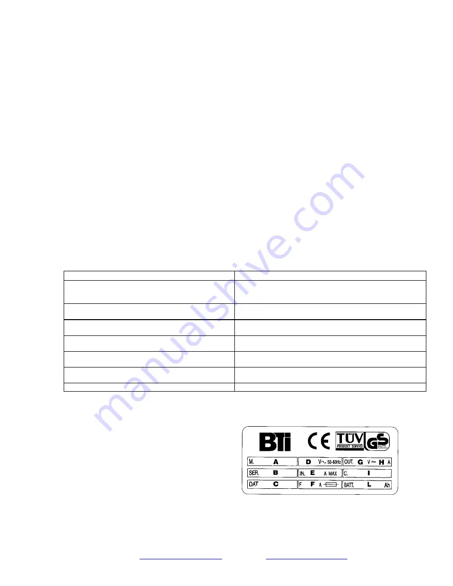
RATING PLATE
The rating plate on the rear of the unit provides the following details:
A – model
B – serial number
C – date of manufacture
D – mains voltage
E – input current
F – fuse rating
G – output voltage (max.)
H – output current (max.)
I – charging curve
L – range of battery sizes possible


