Style Programming (MTC)
SMART MATRIX MTC
2 - 31
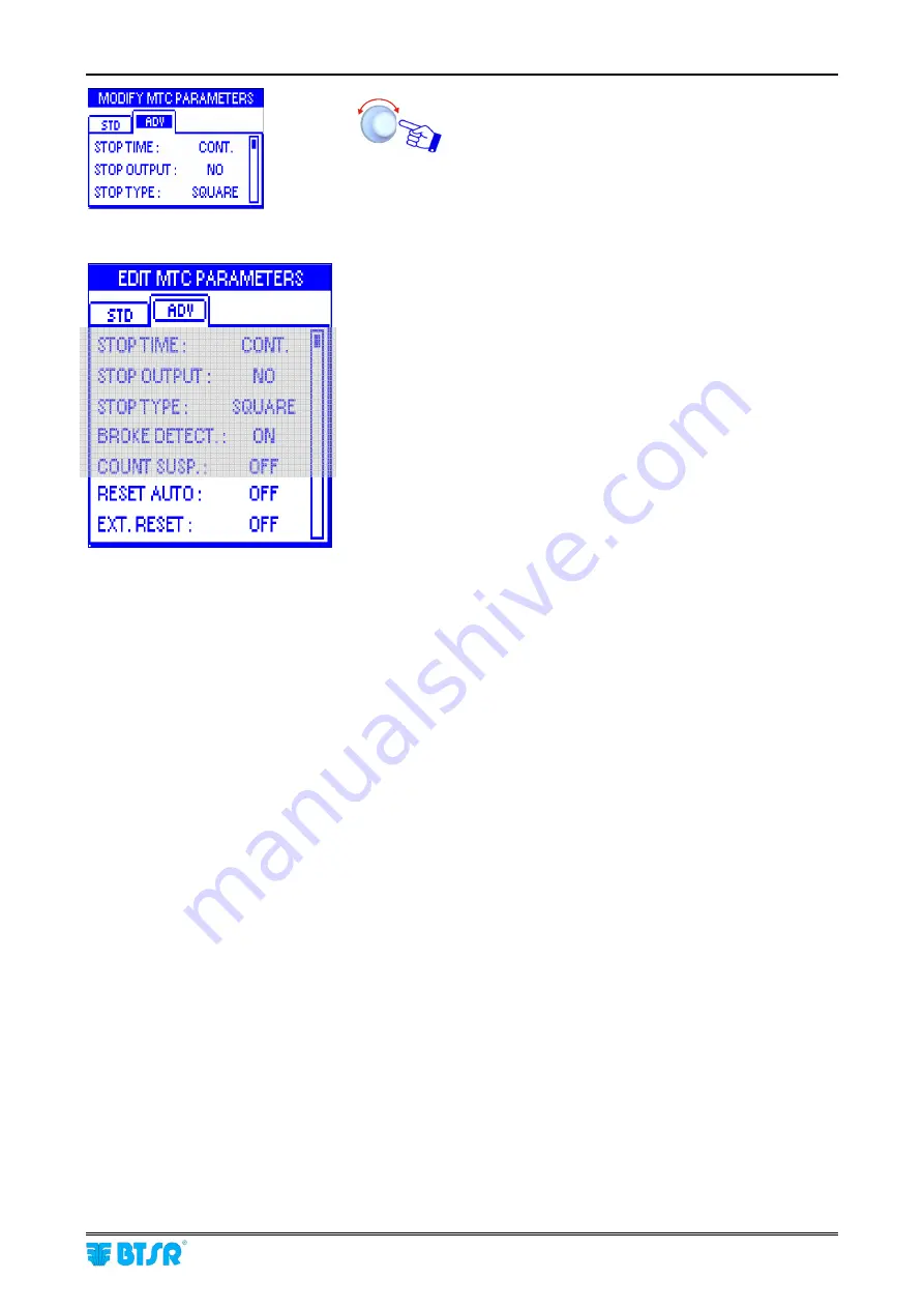
Select and set the each value in the
ADV
window.
STOP TIME
:
This function allows you to choose the
type of signal that will be sent through the STOP
output in case of failure (
i.e. broken yarn
).
The possible choices are:
Continuous
Signal
(
CONT
)
2 seconds Pulse Signal
(
P2s
)
10 seconds Pulse Signal
(
P10s
)
The electrical level of the signal (
either high or low
)
depends on the configuration chosen for the
STOP
OUTPUT
function.
STOP
OUTPUT
: This function allows you to define
the operating mode of the STOP output in order to
meet the application needs. The signal may be
configured as Normally Open (
NO
) or Normally
Closed (
NC
).
STOP TYPE
:
This function allows you to choose the
type of signal that will be sent through the STOP
output when reaching the set Target.
The possible choices are:
Continuous
signal
(
CONT
)
4 Hz square wave form
(
SQUARE
)
The electrical level of the signal (
either high or low
)
depends on the configuration chosen for the
STOP
OUTPUT
function. The
SQUARE
option can be
useful when the SMART terminal is connected to a
machine computer, as it gives the computer itself the
possibility to distinguish between a Target reached
stop and a failure stop.
BROKE DETECTION
:
This function allows you to
enable/disable the yarn broken/missing control
function performed by the sensor.
If the function is enabled (
ON
), then the sensor will
operate both as meter counter and as yarn breakage
control device. Otherwise, if the function is disabled
(
OFF
), the sensor will operate as meter counter
only.
COUNT SUSP
.: when the target is reached or
there’s a broken yarn, the yarn runs still a little bit
because of inertia and this quantity is counted by the
sensor. If the function is
ON
, the counter stops
immediately.
Details about STOP signal timing are
described in “STOP signal timing” paragraph on
section 3
Summary of Contents for SMART MATRIX MTC
Page 1: ...SMART MATRIX MTC Operating Manual ENGLISH Rev 1 0 September 2010 ...
Page 3: ...Introduction i ...
Page 4: ......
Page 9: ...Connections and Electrical Interface 1 ...
Page 10: ......
Page 17: ...Operating Instructions 2 ...
Page 18: ......
Page 71: ...System Information 3 ...
Page 72: ......


