Technical Data and Installation
ULTRAFEEDER
- 2.5 -
2
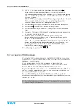
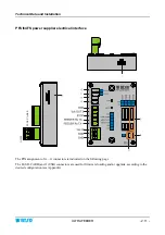
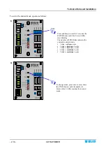
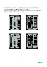
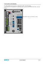
The KTF/PW4 power supply has an analogue exclusion input (
)
connectable to the machine inverter input
(e.g. on MATEC machines).
The analogue exclusion input allows to exclude the ULTRAFEEDER devices
when the machine drops under a determined number of revs/min, i.e. when it
is in the stop phase.
The KTF/PW4 power supply comes with the analogue input already calibrated
for correct operation; however you can change the triggering point of
ULTRAFEEDER exclusion, by adjusting the trimmer
(T).
3
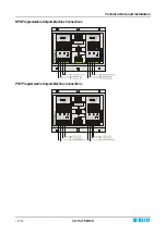
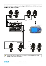
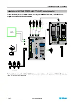
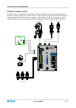
Connect the 24VAC supply terminals to the output of TRF24 transformer.
4
Connect
the terminal to the machine ground potential.
5
Connect the STOP output of both KTF/PW4 groups to the machine STOP
input.
6
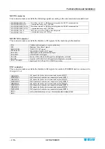
Connect (+ INC) and (+ DEC) terminals to the thread guide common positive
or solenoid valves of the machine.
7
Connect (- INC ) and (- DEC) terminals to a pair of thread guide
programmable outputs or solenoid valves, or use the outputs provided by
BTSR for ULTRAFEEDER devices.
Activate the programmable INC/DEC outputs simultaneously with the thread
guide of yarn under control and keep the commands active for all the yarn
processing time, then deactivate the programmable INC/DEC outputs
simultaneously with the thread guide of yarn.
8
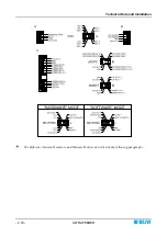
Set the jumper to position
.
Principle of operation of INC/DEC commands
When the INC/DEC commands are active, the ULTRAFEEDER device operates
with the tension value set in
MAIN TENSION
function of P1 menu, and the
ERROR
TENSION
alarm will be active.
When, on the contrary, the INC/DEC commands are deactivated, the
ULTRAFEEDER device operates with the tension value set in
EXIT TENSION
function of P2 menu and the
ERROR
TENSION
will be deactivated.
To gradually adjust the value of tension set in
MAIN TENSION
function of P1 menu,
once the INC/DEC command have been activated, you will have to generate INC
(increment)
or DEC
(decrement)
pulses.
For each INC or DEC pulse, the
MAIN TENSION
value will be respectively
Incremented or Decremented by the amount set in
INC
-
DEC TENSION
function
(last
variable of P1 menu).
For further information on P1 ÷ P4 menu’s programmable functions, please
refer to Chapter 3 –Operation.
Summary of Contents for ULTRAFEEDER
Page 1: ...ULTRAFEEDER YARN CONTROL SYSTEM Operating Manual ENGLISH Rev 4 1 February 2017 ...
Page 40: ...Technical Data and Installation 2 28 ULTRAFEEDER Page intentionally left blank ...
Page 72: ...ULTRAFEEDER Troubleshooting and Maintenance 4 6 ULTRAFEEDER Page intentionally left blank ...
Page 78: ...YTT Device 5 6 ULTRAFEEDER Page intentionally left blank ...

