Technical Data and Installation
ULTRAFEEDER
- 2.13 -
PFU/64FS configuration
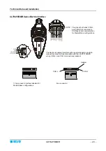
The PFU/64FS interface/power supply board can be configured to operate in 5 different modes, according to
the configuration used (Note 1)
•
Software
Mode
•
Hardware 0
Mode
•
Hardware 1
Mode
•
Emulation 0
Mode
•
Emulation 1
Mode
Each operating mode has different characteristics and a different I/O signal assignment on the board
connectors.
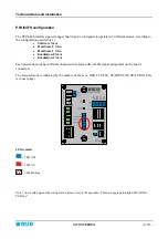
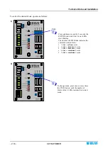
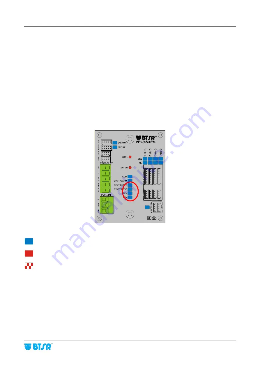
The selected mode is indicated by the number of
blinks on
: NEXT CYCLE, START/STOP, ZPX, PRX LEDs
(see next page)
LED symbols
= LED OFF
= LED ON
= LED blinking
Note 1: to modify/upgrade the configuration, please refer to the appendix “Firmware upgrade through SD-CARD or
USB key”.
Summary of Contents for ULTRAFEEDER
Page 1: ...ULTRAFEEDER YARN CONTROL SYSTEM Operating Manual ENGLISH Rev 4 1 February 2017 ...
Page 40: ...Technical Data and Installation 2 28 ULTRAFEEDER Page intentionally left blank ...
Page 72: ...ULTRAFEEDER Troubleshooting and Maintenance 4 6 ULTRAFEEDER Page intentionally left blank ...
Page 78: ...YTT Device 5 6 ULTRAFEEDER Page intentionally left blank ...

