Operation
- 3-2 -
ULTRAFEEDER
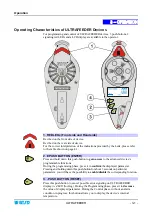
4. + PUSH BUTTON (CONTROL)
Press this push-button to temporarily de-activate the device
(lighting of front/rear
LEDs and of ENTER, RESET, CONTROL push-button LEDs);
press it again to
reactivate the device. This button also allows de-activating
(OFF)
the power unit.
During the programming phase, press it to
increase
the value of displayed
parameter.
Press this push-button whenever you need to operate on the device
(i.e.
for yarn threading, coil separation device adjustment, etc.)
to avoid
undesired start-up of the motor.
During normal operation, the three buttons (ENTER, RESET and CONTROL)
show the green LEDs on , except when the Master/Slave option has been
configured; in this case, infact, the LEDs are used to identify the association
between Master1/2 and the relevant Slaves. For more details, please refer to
“Master/Slave mode” section (Page 3.19).
In case of alarm, the LEDs turn to red.
5. LCD DISPLAY
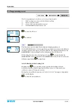
It provides the real time display of measured and adjusted tension values, as well as
the parameters programmable within the various menus, programming and error
messages, device status, etc.
Symbols shown on LCD
A – Label Area
OK
Indicates the activation of any of the 3 push-buttons of ULTRAFEEDER device.
COM
Communication in progress with SMART MATRIX FEEDER/PFU terminal or with the
PC.
CONTROL
Indicates that the ULTRAFEEDER device is operating in Control status.
PROGRAM
Indicates that the ULTRAFEEDER device is in Parameters Programming status.
TARGET
Indicates that the set Target has been reached.
INC
DEC
Indicates with 1 flashing the increment of main tension.
Indicates with 1 flashing the decrement of main tension.
P1
P2
P3
P4
P5
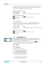
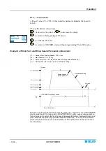
In Control environment indicates that the operating tension is the one defined in P1
(
MAIN TENSION
).
In Control environment indicates that the operating tension is the one defined in P2
(
EXIT TENSION
)
.
Indicates that the device is performing the automatic yarn relax.
Indicates that the UNICO accessory connection has been detected.
Indicates Auto-Offset procedure in progress.
B – Message Area
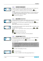
It shows, in the selected language, the various programming menu items, as well as the error messages
during the device operation, the yarn feeding speed
(LFA nnnn)
, the device internal temperature, etc.
Summary of Contents for ULTRAFEEDER
Page 1: ...ULTRAFEEDER YARN CONTROL SYSTEM Operating Manual ENGLISH Rev 4 1 February 2017 ...
Page 40: ...Technical Data and Installation 2 28 ULTRAFEEDER Page intentionally left blank ...
Page 72: ...ULTRAFEEDER Troubleshooting and Maintenance 4 6 ULTRAFEEDER Page intentionally left blank ...
Page 78: ...YTT Device 5 6 ULTRAFEEDER Page intentionally left blank ...

