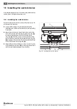
Installing the control device
10
Logano GE515 - We reserve the right to make any changes due to technical modifications.
47
10.2 Installing the temperature sensor set
and burner cable
z
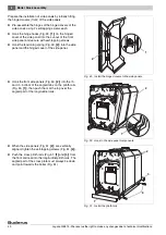
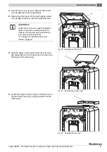
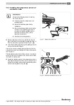
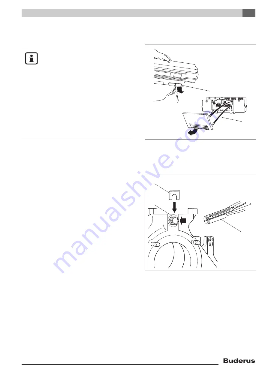
Where necessary remove any knockouts (Fig. 61,
[1]
) in the back of the cable duct (Logamatic 33xx) or
from the rear wall (Logamatic 43xx) (Fig. 61,
[2]
).
z
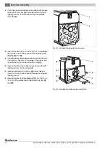
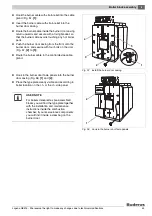
Insert the capillary pipes through the cable gland and
unroll to the required length.
The sensor well has already been sealed into the flow
connection coupler (see chapter 8.5 "Seal-in the sensor
well", page 27).
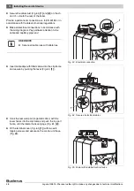
The temperature sensor set (three sensors, one sensor
blank Fig. 62,
[1]
) connected to the control unit is fitted
into the R ¾" sensor well.
z
Route the capillary sensor to the measuring point on
the boiler and insert it into the sensor well as far as it
will go (Fig. 62,
[2]
); then secure the assembly with a
sensor securing device (Fig. 62,
[3]
).
Fig. 61 Prepare the cable duct
2
1
USER NOTE
Observe the following when connecting
the control device:
z
Carefully route the cable ducts and
capillary pipes.
z
Never kink capillary pipes during
installation.
z
Work on heating systems must only be
carried out by qualified personnel. If
you are not suitably qualified, let an
electrical contractor carry out the
electrical connections.
z
Observe all local regulations.
Fig. 62 Install the temperature sensor set
1
2
1
2
3

