background image

6


Installation

Logano plus GB402 - Subject to technical modifications!

21

6.5

Making the heating circuit connection

6.5.1

Connecting the flow

B

Insert a gasket between the flange on the boiler and the 
threaded mating flange on the flow.

B

Secure the flange connection with 4 screws, washers 
and nuts.

Fig. 13 Fitting the flow (VK)

6.5.2

Installing the safety assembly (on site)

B

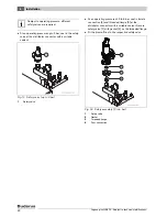
Seal in distributor [2] at flow connector [1] using a 
suitable sealant.

B

Remove the union at the cap valve fitting [3].

B

Fit union with gasket to connector of fitting manifold [4] 
and secure to the cap valve on the distributor.

B

Level the fitting manifold and fit maximum pressure 
limiter [5].

Fig. 14 Installing the fitting manifold

1

Flow connector

2

Distributor

3

Cap valve

4

Fitting manifold complete with cap valve ¾ Inch

5

Maximum pressure limiter

NOTICE: 

System damage due to leaking 

connections!

B

Install all lines free from stress to the boiler 
connections.

B

Use new gaskets if fittings need to be 
undone.

B

Only tighten flanges on the heating flow 
and return after the connections have been 
made.

B

Before installing the pipe connections, 
check connections and gaskets on the 
boiler for possible damage.

Boiler flow (VK)

Boiler return (RK)

DN80

PN6 standard flange EN1092

Tab. 8

Water connection dimensions

NOTICE: 

System damage through incorrect 

installation.

B

Always fit a safety valve and the automatic 
air vent valve or the safety assembly to the 
flow.

The safety assembly (accessory) comprises 
an automatic air vent valve and a pressure 
gauge. As an option, it may be converted for 
use with a safety valve (additional accessory) 
and a fitting manifold for the maximum 
pressure limiter.
If these accessories are not used, a safety 
valve, pressure gauge and an automatic air 
vent valve must generally be installed in the 
flow, upstream of the first shut-off valve.

Summary of Contents for Logano plus GB402

Page 1: ...For contractors Read carefully prior to installation and maintenance Installation and maintenance instructions Gas condensing boiler Logano plus GB402 6 720 646 410 10 2010 GB ...

Page 2: ...cylinder 23 6 6 Filling the heating system and checking for leaks 24 6 7 Making the electrical connection 25 6 7 1 Installing the control unit 25 6 7 2 Making the power supply connection 26 6 8 Fuel connection 27 7 Commissioning the heating system 28 7 1 Checking the operating pressure 28 7 2 Checking for leaks 29 7 3 Recording gas characteristics 29 7 4 Check the system equipment level 30 7 5 Pur...

Page 3: ... 49 9 9 Refitting detached parts 49 9 9 1 Fitting the fan 50 9 9 2 Fitting the ventilation air collector and the gas valve 50 9 9 3 Installing the burner 50 9 9 4 Fitting the gas line to the gas valve 50 9 9 5 Fitting the ventilation air unit 51 9 10 Checking for leaks during operation 51 9 11 Checking the ionisation current 51 9 12 Completing inspection and maintenance 51 9 12 1Removing meters 51...

Page 4: ...tractor Risk of poisoning An insufficient supply of air can result in dangerous escape of flue gas B Never block ventilation and extract air apertures or reduce their size B The boiler must not be operated unless you immediately remedy the fault B Inform the system operator in writing of the problem and associated risk Risk from escaping gases B Ensure that the flue pipes and seals are not damaged...

Page 5: ...er or reduce the size of ventilation openings in doors windows and walls If draught proof windows are fitted ensure there is an adequate supply of combustion air B Never shut off safety valves Water may be expelled from the heating circuit and DHW pipework during heat up Risk of damage due to operator error Operator errors can result in injury and damage to property B Ensure that children never op...

Page 6: ...ice instructions are designed for contractors who through their technical training and experience are knowledgeable in handling heating systems and gas installations The following documents are available for the Logano plus GB402 Operating instructions Operating instructions MC10 control unit Installation and maintenance instructions Operator s log Technical guide The above documents are also avai...

Page 7: ...C10 4 Gas burner burner rod 5 Boiler block with thermal insulation 6 Boiler casing 7 Condensate tray and siphon 8 Burner control unit The main components of the Logano plus GB402 Æ Fig 1 are Control unit Appliance frame and casing Boiler block with thermal insulation Gas burner The control unit monitors and controls all electrical boiler components The boiler block transfers the heat generated by ...

Page 8: ...atus display key 11 Flue gas test key 12 Reset button Logamatic BC10 base controller Æ Fig 2 The Logamatic BC10 base controller provides control over the standard functions of the heating system It provides functions including the following Switching the heating system ON and OFF DHW temperature default and maximum boiler water temperature in heating mode Status display Fig 2 provides an overview ...

Page 9: ... regarding suitable accessories see the catalogue The following accessories are available from your local sales office Safety valve or safety assembly Flue gas system Ventilation air system Programming unit e g RC35 Silencer Ventilation air adaptor accessory for balanced flue operation Packing unit Component Packaging 1 boiler Assembled boiler excluding casing 1 shrink wrap package on a pallet Sip...

Page 10: ...s Fig 3 Dimensions and connections for the Logano plus GB402 dimensions in mm AA Flue gas outlet AKO Condensate outlet EV Combustion air pipe inlet balanced flue operation only GAS Gas connection MAG Optional connection for a diaphragm expansion vessel to protect a single boiler RK Boiler return ST Safety valve or safety assembly connection VK Boiler flow ...

Page 11: ...e bar 6 Pipework connections Gas connection Inches 2 Heating water connection DN mm 80 Condensate connection Inches Flue gas values Flue gas connection mm 250 Volume of condensate for natural gas G20 40 30 C l h 30 8 39 2 46 2 55 9 64 7 Flue gas mass flow rate Full load g s 142 4 174 5 207 1 240 6 271 9 Partial load g s 28 7 36 8 40 6 48 0 53 2 Flue gas temperature 50 30 C Full load C 45 44 44 43 ...

Page 12: ...he boiler or corresponding gas type conversion kits supplied Delivered set to the mains supply pressure in mbar 1 DE 320 620 20 I 2ELL G20 G25 20 AT CH SK 320 620 20 I 2H G20 20 ES GB IE IT PT SI 320 620 20 I 2H G20 20 EE DK HR NO SE 320 620 20 I 2H G20 20 FR 320 620 20 25 I 2ESi G20 20 BE 320 620 20 25 I 2E R B G20 20 CZ 320 620 20 I 2H G20 20 LU 320 620 20 I 2E G20 20 NL 320 620 25 I 2L G25 25 P...

Page 13: ...ncing installation inform the local flue gas inspector where appropriate and water authority 3 4 Heating water quality As pure water cannot be used for the heat transfer water quality is important Poor water quality can damage heating systems due to scale formation and corrosion 3 5 Combustion air connection flue connection The installation room must be equipped with the required combustion air ap...

Page 14: ... the boiler by means of a crane hoist forklift truck or transport rollers B Only trained authorised personnel may undertake the handling e g by forklift truck or lifting by means of a crane hoist B Observe safety instructions relating to the lifting of heavy loads e g by means of a crane hoist B Wear personal safety equipment e g safety boots and protective gloves B Protect the boiler against slip...

Page 15: ...s and carefully transport it to the installation room Fig 6 Transporting the boiler on rollers measurements in mm NOTICE Boiler damage through impact The boiler is at risk of tipping over if it is pushed off the side of the pallet B Push the boiler off the pallet towards the burner or flue gas side When pushing the boiler from the flue gas side remove fixing bar 2 B Prevent the boiler from coming ...

Page 16: ...tore combustible materials paper curtains clothing thinners paints etc in the vicinity of the boiler NOTICE Risk of boiler damage from contaminated combustion air B Never use chlorinated cleaning agents or halogenated hydrocarbons as contained in spray cans solvents cleaning agents paints and adhesives for example B Never store or use such materials in the boiler room B Avoid very dusty atmosphere...

Page 17: ...le condensate to drain fully from the condensate tray B Bring the boiler into its final position B Level the boiler horizontally by means of its adjustable feet and a spirit level Fig 8 Levelling the boiler CAUTION Boiler damage through insufficient load bearing capacity of the installation area or inadequate substrate B Ensure that the installation area offers sufficient load bearing capacity ...

Page 18: ...ection During engineering and installation of the flue create a layout that best favours the flue gas flow Flue gas routing on multi boiler systems cascade These instructions only concern single boiler systems Only ask qualified contractors to calculate and size flue gas combustion air systems for multi boiler systems Ask the manufacturer of the flue system to confirm and verify the calculations T...

Page 19: ...e tray 3 Condensate hose connection to the flue gas system 4 Elbow filler hole 5 Siphon outlet to neutralising system or drain line 6 Siphon B Make the connection to the sewerage system in accordance with the instructions of the neutralising system and locally applicable regulations Information regarding the condensate hose B Carefully drain the condensate created inside the boiler and flue route ...

Page 20: ...race and seal with sealant accessory B Insert and seal in a ventilation air bend in the adaptor B In cascade arrangements ensure that the boiler is equipped with a separate ventilation air line B Create the ventilation air line up to the ventilation air bend using a standard air supply system in accordance with the requirements of the country concerned Fig 12 Ventilation air connection for balance...

Page 21: ...iter NOTICE System damage due to leaking connections B Install all lines free from stress to the boiler connections B Use new gaskets if fittings need to be undone B Only tighten flanges on the heating flow and return after the connections have been made B Before installing the pipe connections check connections and gaskets on the boiler for possible damage Boiler flow VK Boiler return RK DN80 PN6...

Page 22: ...ety valve B At an operating pressure of 3 to 6 bar seal in female connection 4 and threaded flange 3 at the distributor connector with a suitable sealant Secure safety valve 1 with gasket 2 on the threaded flange B Fit the blow off line to the respective safety valve Fig 16 Safety assembly 3 to 6 bar 1 Safety valve 2 Gasket 3 Threaded flange 4 Fem connection Subject to operating pressure different...

Page 23: ...expansion vessel DEV To safeguard individual boilers a DEV can be connected to the inch connection on the return in accordance with EN 12828 B Install the DEV on site to maintain the system pressure in the return upstream of the pump Connecting the drain fill valve on site B Install a drain fill valve in the return 6 5 4 Installing a DHW cylinder Make the connection of a DHW cylinder to the flow a...

Page 24: ...in accordance with locally applicable regulations B Once the heating system has been tested and no leaks have been found set the correct operating pressure NOTICE System damage through boiler scaling B Note the information specified in the operator s log NOTICE Risk of system damage from excess pressure when testing for leaks Pressure control and safety equipment may be damaged by excessive pressu...

Page 25: ...er B Let the resilient hooks of the control unit click into the openings by pushing the control unit Fig 20 Fitting the control unit Logamatic MC10 DANGER Risk to life from electric shock B Prior to all electrical installation work isolate all poles of the power supply and secure against unintentional reconnection Observe the following points regarding the electrical connection B Electrical work o...

Page 26: ...ing cables with cable clips DANGER Risk to life from electric shock Incorrectly terminated cables can result in faulty operation and possible dangerous consequences B When making the electrical connections observe the connection diagram of the MC10 and its installation instructions part of the standard delivery of the control unit DANGER Risk of fire through hot boiler components Hot components ma...

Page 27: ...or 1 recommended to the gas tap B Connect the gas line to the gas connection free of stress B Secure the gas line with pipe clips so that the gas connection is free from any stresses B Close the gas tap Fig 25 Gas connection 1 Compensator 2 Gas tap here with thermally activated shut off equipment 3 Pipe clip Observe the installation instructions of the function module 7 747 010 720 35 1RS DANGER R...

Page 28: ... water via the on site drain fill valve until the required operating pressure has been reached B During filling vent the heating system via the radiator bleed valves NOTICE Boiler damage through excessive dust and dirt contamination in open flue operation Strong dust and dirt contamination can occur for example due to building work in the installation room B During building work operate the boiler...

Page 29: ...index and calorific value and record these in the commissioning report Æ Chapter 7 18 page 38 DANGER Risk of explosion There is a risk of explosion if gas lines and gas connections leak B Carry out an appropriate tightness test with a foaming agent DANGER Risk of system damage due to short circuit B Cover the areas at risk before performing a tightness test e g the internal water pressure sensor a...

Page 30: ... EE ES FR GB GR HR HU IE IT LU NO PL PT RO RU SE SI SK UA Natural gas H or E G20 Factory set ready for use The gas valve is adjusted and sealed Wobbe index for 15 C 1013 mbar Adjusted to 14 1 kWh m3 Applicable for 11 4 to 15 2 kWh m3 Wobbe index for 0 C 1013 mbar Adjusted to 14 9 kWh m3 Applicable for 12 0 to 16 1 kWh m3 DE Natural gas L Factory set ready for use The gas valve is adjusted and seal...

Page 31: ...mply with locally applicable regulations or those of your gas supply utility Have any faults removed immediately B Check that the flue connection complies with all current regulations Æ Chapter 6 1 page 18 B Have any faults removed immediately 7 7 Preparing the heating system for operation B Open the fuel supply at the main shut off valve and upstream of the gas valve B Switch on the heating syste...

Page 32: ...shows the current boiler water temperature in C If fault message A11 appears set the date and time on the RC35 programming unit Only then will the current boiler water temperature be displayed Before continuing with further commissioning steps set the correct parameters on the RC35 programming unit In particular the DHW heating configuration heating circuit pump and cylinder primary pump must be s...

Page 33: ...he gas supply pressure falls outside the values in Tab 10 shut down the boiler and notify the gas supply utility B Remove the test hose B Carefully tighten the threaded plug on the test nipple for gas supply pressure Fig 31 Testing the gas supply pressure 1 Pressure test nipple for testing the gas supply pressure and for venting SERVICE MENU quick operation settings diagnosis servicing B SERVICE D...

Page 34: ...ull load 1 High load adjusting screw 7 10 2 Setting and checking the CO2 values under partial load B Press until the decimal point in the status display illuminates min 2 seconds This turns on the flue gas test B Hold down and simultaneously for approx 5 seconds Fig 33 Accessing partial load at the BC10 With standard settings the display shows B Press to reduce the boiler output in percent until L...

Page 35: ...ing mode on the RC35 B Close the flap on the RC35 B If the boiler is designed for operation with the Logamatic 4000 control system remove the RC35 again Starting the Logamatic 4000 control system 7 13 Recording actual values B Carry out the following tests at a test port in the boiler flue connection and enter the results in the commissioning report Æ Chapter 7 18 Draught Flue gas temperature tA A...

Page 36: ...the value into the commissioning report Æ Chapter 7 18 To ensure fault free operation the ionisation current at partial and full load and with burning flame should be at least 15 μA B Return to operating mode on the RC35 B Close the flap on the RC35 7 15 Checking for leaks during operation B With the burner operational use a foaming agent to test all sealed points in the entire burner gas train su...

Page 37: ...the top B With locking screws secure the top of the front panel 1 to the boiler B Affix the clear pocket containing the technical documentation in a clearly visible spot on the side of the boiler Fig 37 Installing casing parts 1 Front 2 Front side panels incl thermal insulation 3 Rear side panels excl thermal insulation 7 17 Informing the owner operator and handing over technical documentation B F...

Page 38: ...nection 31 7 Check the system equipment level 30 8 Commission the control unit and burner 32 9 Adjust gas type if required 31 10 Record actual values 35 Full load Partial load Draught _______Pa _______Pa Gross flue gas temperature tA ______ C ______ C Air temperature tL ______ C ______ C Net flue gas temperature tA tL ______ C ______ C Carbon dioxide content CO2 or oxygen content O2 _______ ______...

Page 39: ... customer what to do in an emergency e g a fire B Never risk your own life Your own safety is paramount B Close the main fuel shut off valve B Isolate the heating system from the mains power supply by means of the heating system emergency stop switch or the appropriate domestic fuse circuit breaker NOTICE System damage due to frost When the heating system is switched off it can freeze up if there ...

Page 40: ...vicing B Shut down the heating system B Undo the locking screw from the top centre of the boiler front panel B Slightly lift the front panel and remove by pulling forwards Fig 39 Removing the front panel 1 Front 9 2 General work The following work is not described in any further detail in this document It must nevertheless still be carried out B Check the general condition of the heating system B ...

Page 41: ... in inches in metres 1 1 1 2 1 0 2 0 4 0 6 1 0 1 4 2 2 2 0 4 0 7 1 2 2 0 2 7 4 4 3 0 6 1 1 1 7 3 0 4 1 6 6 4 0 8 1 5 2 3 4 0 5 5 8 8 5 1 0 1 8 2 9 5 1 6 9 11 0 6 1 2 2 2 3 5 6 1 8 2 13 2 7 1 4 2 5 4 1 7 1 9 6 15 4 8 1 6 2 9 4 6 8 1 11 0 17 6 9 1 8 3 3 5 2 9 1 12 4 19 8 10 2 0 3 6 5 8 10 1 13 7 22 0 Tab 13 Pipework volume Vpipe subject to pipe length and diameter Pipe length Pipework volume Vpipe i...

Page 42: ... restrictions 3 Range Valve leaks valve may not be used check as described in the following Read off example test volume Vtest 5 litres and pressure drop 4 mbar min range 3 Valve leaks valve may not be used check as described in the following If the read off point for test volume Vtest and pressure drop per minute lies within the range Valve leaks see read off example carry out the test described ...

Page 43: ...7 10 to 7 10 2 NOTICE System damage If the heating system is filled when hot the resulting temperature stresses can cause stress cracks The boiler will then leak B Only fill the heating system when cold the flow temperature should not exceed 40 C B When the heating system is in operation never fill it via the boiler drain fill valve Instead only use the filling valve in the heating system pipework...

Page 44: ...e boiler to cool down B Remove siphon 2 from the outlet of condensate tray 1 and position a bucket underneath the tray Fig 43 Removing the siphon 1 Condensate tray outlet 2 Siphon 9 6 1 Removing and cleaning burner B Undo toggle clip 1 at the top of the ventilation air hose B Pull off ventilation air hose 2 together with the connector from ventilation air collector 3 Fig 44 Undoing the ventilation...

Page 45: ...e manifold B Undo the electrical connections at the gas valve and the fan Æ Fig 56 page 48 B Carefully pull out the burner towards you Fig 47 Undoing the nuts at the mixture manifold 1 Fixing nuts with washer B Undo all 4 screws 1 between the mixture manifold and the carriage Fig 48 Undoing the mixture manifold from the carriage 1 Screws and locknuts B Pull out the burner together with the mixture...

Page 46: ... exchanger horizontally and diagonally using the long cleaning blade B Clean the back section of the hot gas flues from below through the condensate tray using the short cleaning blade Fig 52 Dry cleaning the heat exchanger 1 Long cleaning blade available separately 2 Short cleaning blade available separately B Screw the cleaning covers back on Fig 53 View of cleaning cover 1 320 kW 2 395 620 kW C...

Page 47: ...phon for free flow 9 7 Inspecting the burner electrodes Checking the electrode position B Move the burner into its service position Æ Chapter 9 6 B Check the gaps between the electrodes and compare them with those shown in Fig 55 Fig 55 Setting the electrode position 1 Gasket O ring mixture manifold 2 Fixing screws burner rod 3 Ignition electrode 4 Burner rod 5 Ionisation electrode B Replace the e...

Page 48: ...ilation air hose together with the connector from the ventilation air collector B Undo cables 3 from the gas valve B Undo 4 screws 2 from the gas valve flange Fig 56 Undoing the gas valve connections 1 Compensation hose 2 Screws 3 Cables B Remove 3 nuts 2 from the nozzle plate and remove gas valve 1 Fig 57 Undoing the gas valve 1 Gas valve 2 Nut 9 8 2 Changing the gas filter B Undo both screws 4 f...

Page 49: ... Front semi shell B Remove rear semi shell 1 Fig 60 Removing the rear semi shell 1 Semi shell B Remove mounting plate 1 from the fan B Undo both rear screws 3 joint between carriage 2 and fan 5 do not remove B Support the fan and remove both front screws 4 B Pull out the fan towards the front Fig 61 Dissembling the components of the ventilation air collector 1 Mounting plate 2 Carriage 3 Rear scre...

Page 50: ...rner B Insert the gasket on the top of the carriage B Insert the O ring into the mixture manifold B Insert the burner together with the mixture manifold into the boiler combustion chamber B Push the carriage towards the boiler block B Secure the mixture manifold on the carriage using 4 screws B Secure the mixture manifold at the front section of the boiler using 4 nuts B Plug all necessary cables ...

Page 51: ...xpiry of the specified time in use NOTICE System damage through contaminated air B Prior to fitting the ventilation air hose check the ventilation air grille integrated into the lower hose adaptor for contamination and clean if required NOTICE Risk of system damage due to short circuit B Cover the fan and other areas at risk prior to commencing the leak detection B Never spray the leak detection a...

Page 52: ...or contamination shut down the heating system for this step 6 Check the siphon and the condensate tray shut down the heating system for this step 7 Check electrode block shut down the heating system for this step 47 8 Check the gas supply pressure 33 9 Check the ventilation and extract air apertures and the flue connection 31 10 Record actual values 35 Draught ________Pa ________Pa ________Pa ____...

Page 53: ...tion ________ 4 5 6 7 8 9 10 ________Pa ________Pa ________Pa ________Pa ________Pa ________Pa ________Pa ________Pa ________ C ________ C ________ C ________ C ________ C ________ C ________ C ________ C ________ C ________ C ________ C ________ C ________ C ________ C ________ C ________ C ________ C ________ C ________ C ________ C ________ C ________ C ________ C ________ C _________ _________...

Page 54: ...over of the heat exchanger 46 4 Replace the electrode block 47 5 Clean the siphon 47 6 Clean the condensate tray 47 7 Replace the mixture manifold gasket O ring 47 8 Carry out a function check Confirm professional service Company stamp signature Tab 18 Date ______ Date ______ Date ______ Date ______ Date ______ 1 2 3 4 5 6 7 8 Company stamp signature Company stamp signature Company stamp signature...

Page 55: ...s and remedial measures see the control unit Æ documentation and the following Chapter 10 2 B Hold down Reset for 5 seconds to clear the fault The reset is only possible if a fault message is flashing The display shows rE whilst the reset is being implemented If the display then reverts to a standard operating message the fault has been eliminated Should the fault recur repeat the reset two or thr...

Page 56: ...ching optimisation time Appliance in cycle block The standard switching optimisation time is 10 min Check output setting at the BC10 base controller Match the boiler output to the required heat demand of the building Check the control setting in the RC35 control unit Match the control setting to the system conditions OH The appliance is in standby mode there is no heat demand The boiler is ready t...

Page 57: ...re cause Action B 2E 207 Water pressure 0 6 bar Check whether the heating system pressure is at least 1 bar Correct the operating pressure V 2U 533 Incorrect hydraulic connection of boiler or pump The boiler control unit has recognised an incorrect flow on the water side Check that the boiler flow and return have not been swapped Check pump for correct flow direction Connect flow and return correc...

Page 58: ...h fan speed The detected speed is higher than the specified speed Check PWM signal SAFe cabling for contact separation breaks and damage Check plug in connections for damage Make the contacts correctly Replace cable if required Replace fan V 4A 520 Intelligent high limit safety cut out flow The flow temperature has reached a value of 100 C The temperature rise is monitored by the boiler sensor Con...

Page 59: ...nections Check the resistances at the boiler sensor according to table or visually inspect the plug at the temperature sensor Replace the boiler sensor if the sensor values deviate from the stated values or if the plug is faulty Check the voltage values on the boiler sensor according to table Replace the SAFe if there are deviations V 4U 522 Boiler sensor short circuit between temperature sensors ...

Page 60: ...k the plug in connection Clean or replace if contaminated Replace in case of damage Refit plug it is found to be loose Check sensor values according to table Replace the temperature sensor in case of deviations Check the voltage at the temperature sensor according to table SAFe documentation Replace the SAFe in case of deviations V 4A 575 Intelligent high limit safety cut out responds The boiler f...

Page 61: ...e SAFe or the MC10 that is faulty Replace the SAFe or MC10 If the SAFe remains dark wait a short time as the appliance will not start up if the SAFe is cold Wait up to 30 minutes and check whether the green indicator on the SAFe illuminates again Replace the SAFe if that is not the case B 6L 515 Ionisation signal failure during operation Ionisation signal failure during burner operation None the S...

Page 62: ...lace ignition ionisation electrode Check cabling between the SAFe and the ionisation electrode for contact separation breaks and damage Make the contacts correctly Replace cable if required Check electrode gaps and ignition ionisation electrode for damage Align burner rod or electrode Replace faulty electrode Check cabling between the ignition transformer and ignition electrode for contact separat...

Page 63: ...attempts at starting then there is a delay of one hour before making three more start attempts Check that the gas tap is open Replace the gas valve if required Check whether there is gas pressure Check the gas pressure Check whether the flue gas pressure limiter has responded Reset the flue gas pressure limiter Check the flue for blockages Check electrode Replace electrode if required Check igniti...

Page 64: ...circuit The control unit receives unrealistic values from the return sensor Check cabling between SAFe and return sensor Replace cable if required Check electrical connection of the SAFe cable Remedy contact problem if required Check resistance values of temperature sensor according to table Replace temperature sensor if required Check voltage at the temperature sensor terminals inside the SAFe ac...

Page 65: ... SAFe and flow temperature sensor Replace cable if required Check electrical connection of the SAFe cable Remedy contact problem if required Check resistance values of temperature sensor according to table Replace temperature sensor if required Check voltage at the temperature sensor terminals inside the SAFe according to table Replace SAFe if resistance values of the temperature sensor are correc...

Page 66: ...ensor in case of deviations Check the voltage at the temperature sensor according to table Replace the SAFe in case of deviations V EE 612 Return temperature sensor measurement Successive measurements of the return temperature deviate severely from each other Check the boiler sensor lead Replace in case of damage Clean or replace if contaminated Check the plug in connection Refit plug it is found ...

Page 67: ...curves depict mean values and are subject to tolerances Measure the resistance at the cable ends Fig 65 Sensor curves boiler sensor x Resistance in Ω y Temperature in C DANGER Risk to life from electric shock B Isolate the heating system before taking any readings Two identical sensors dual sensors installed in one sensor casing are used as boiler sensors All temperature sensors on the GB402 have ...

Page 68: ...d power supply no plug in connection B Ensure the power is connected to the correct phases B Implement the installation fuse protection mains isolator emergency stop switch and protective measures in accordance with local regulations DANGER Risk to life from electric shock B Never use the earth conductor yellow green as control line NOTICE Operating faults through power failure B When connecting e...

Page 69: ...11 Appendix Logano plus GB402 Subject to technical modifications 69 Fig 67 MC10 connection diagram 1 The total current of all externally connected components must not exceed 5 A ...

Page 70: ...pump 12 PH HK1 Heating circuit pump 13 WA Heat demand external 14 FA Outside temperature sensor 15 FW DHW temperature sensor 16 EV external interlock remove jumper during connection 17 RC Room controller 18 EMS BUS cable EMS connection to function modules 19 SAFe BUS cable SAFe connection to the burner control unit 20 Low voltages 21 Control voltage 230 V Fig 68 Available versions BC10 A Fuse insi...

Page 71: ...connection diagram Fig 69 SAFe connection diagram 1 Fan PWM signal 2 Ignition transformer 3 Ionisation 4 Gas solenoid valve MV1 MV2 5 Gas pressure switch 6 Mains entry 7 Water pressure sensor 8 Flue gas pressure limiter 9 Flow temperature sensor 10 Return sensor 11 Boiler sensor ...

Page 72: ...connection 27 Fuels 11 G Gas category 11 H Handling 14 I Installation room 16 Ionisation current 51 L Leak testing gas 51 Levelling 17 O Operating pressure maximum 11 P Packaging 9 Product description 7 R RC35 programming unit 51 Regulations 13 Removing the burner 44 Reports inspection and maintenance 52 S Safety precautions 4 Standards 13 T Three way valve 25 Type of construction 11 Type of curre...

Page 73: ...Logano plus GB402 Subject to technical modifications 73 Notes ...

Page 74: ...Logano plus GB402 Subject to technical modifications 74 Notes ...

Page 75: ...Logano plus GB402 Subject to technical modifications 75 Notes ...

Page 76: ...wold Way Warndon Worcester WR4 9SW Customer service 0844 892 3004 Technical support 0844 892 4224 Fax 01905 753130 www buderus commercial co uk In the UK and IE Buderus is a brand name of Bosch Thermotechnology Ltd ...

Reviews: