3
Information on installation and operation
Logano plus SB325 – 6 720 806 328 (2013/07)
13
Control unit settings
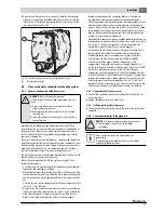
Fig. 6 Control unit settings
[1]
High limit safety cut-out
[2]
Temperature control unit
[3]
MEC
▶ Select temperatures (
Tab. 10, page 12) at high limit safety cut-out
[1] in the control unit and at temperature controller [2].
▶ Select the maximum boiler water temperature at the MEC [3].
Example DHW demand:
Sum of the set DHW temperature (60 °C) and parameter "Boiler rise"
(20 °C) in the "DHW" menu:
60 °C + 20 °C = Maximum temperature demand 80 °C
Example heating circuits:
Sum of the set temperature of the heating circuit with mixer with the
highest temperature required (70 °C) and parameter "Boiler rise" (5 °C)
in the "Heating circuit data" menu:
70 °C + 5 °C = Maximum temperature demand 75 °C
Notes on setting third party control units
• The third party control unit (building management system or PLC
controllers) must ensure a maximum internal boiler water
temperature that is sufficiently different from the high limit safety cut-
out. It must also be ensured that the control electronics rather than
the boiler water controller switch the burner on and off.
• The control unit must ensure that the burner is switched to low load
before being shut down. If this is not observed, the safety shut-off
valve (SAV) in the gas train may lock out.
• Select control equipment that allows a gentle start-up with a time
delay when the system is cold.
• After the burner enable, an automatic timer (for example) should limit
the burner to low load for a period of approx. 180 seconds.
A restricted heat demand will prevent uncontrolled cycling of the
burner.
• It must be possible to show the number of burner starts on the control
unit used (or alternatively on the burner control unit).
6 720 648 053-38.2T
1
2
3
80
The maximum temperature demand is not a value that is
directly selected. The maximum temperature demand is
composed of the set temperature and the rise.
All maximum temperature demands must always be 7 K
below the maximum selected boiler water temperature.
NOTICE:
System damage due to incorrect sensor
position!
The sensors of the high limit safety cut-out (STB) and of
the thermostat (TR)
must
be fitted at the installation
location (
Fig. 31, page 26) on the top of the boiler.
▶ In the case of third party control units, match the
sensor immersion sleeve to the diameter of the
sensors used.
▶ Do not change the length of the immersion sleeve.
Observe the operating conditions in chapter 2.7, page 5
and observe chapter 5.13, page 26 when installing
sensors.
Unit
Value
Maximum time constant of temperature
controller
s
40
Maximum time constant on pressure switch/
limiter
s
40
Minimum temperature difference between
burner turning on and off
K
7
Tab. 11 Conditions of use


