background image

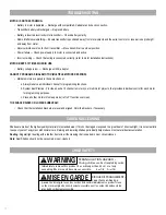
DUAL SHADES

Smart Home Collection Motorization

Thank you for your purchase. This shade has been custom built for you from the highest quality materials.  

To avoid errors and save valuable time, please read these instructions before installing your new shades.

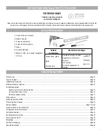
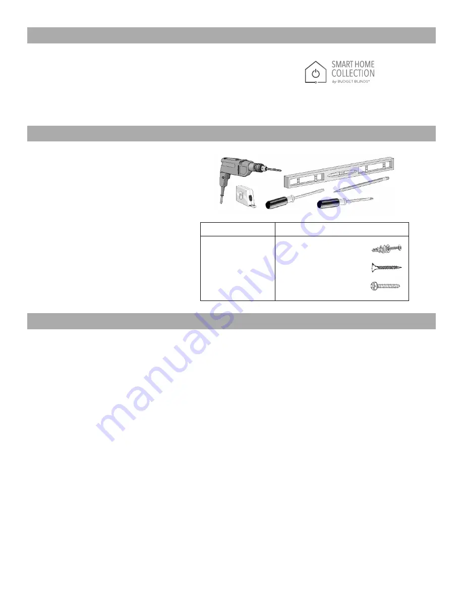
1.  Pencil or Marker
2.  Measuring Tape
3.  Flat Blade Screwdriver
4.  Phillips Screwdriver
5.  Level
6.  Power Drill
7.  3/32” Drill Bit & 1/4” Hex Nut Driver Bit

1

Getting Started  ................................................................................................................................................................................................ Page 2
Mounting Type  ................................................................................................................................................................................................. Page 2
Bracket Installation  .......................................................................................................................................................................................... Page 2
Inside and Outside Mount  ................................................................................................................................................................................ Page 2
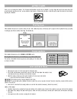
Initial Set Up
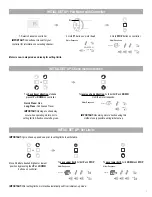
        Pair Motor with Controller  ......................................................................................................................................................................... Page 3
        Check Motor Direction  .............................................................................................................................................................................. Page 3
        Set Limits  .................................................................................................................................................................................................. Page 3
Sleep Mode  ..................................................................................................................................................................................................... Page 4
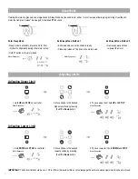
Adjusting Limits  ............................................................................................................................................................................................... Page 4
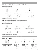
Controllers and Channels  ................................................................................................................................................................................ Page 5
Favorite Position  ........................................................................................................................................................................................... Page 5-6
Adjusting Speed  .............................................................................................................................................................................................. Page 6

Soft Spot Configuration 

 ................................................................................................................................................................................... Page 7

Battery Check Function  ................................................................................................................................................................................... Page 8
Charging the Motor Battery  ............................................................................................................................................................................. Page 8
P1 Button Functions  ........................................................................................................................................................................................ Page 9
Troubleshooting  ............................................................................................................................................................................................. Page 10
Care and Cleaning  ......................................................................................................................................................................................... Page 10
Child Safety  ................................................................................................................................................................................................... Page 10

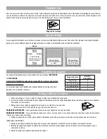
Mounting Surface

Fastener

Drywall, Plaster

Wall Anchors, Expansion Bolts

(Not provided)

Metal

Sheet Metal Screws

(Not provided)

Wood

No. 6 Hex Head Screws

(Provided)

INSTALLATION & OPERATING INSTRUCTIONS

TOOLS YOU WILL NEED

TABLE OF CONTENTS

Summary of Contents for SMART HOME COLLECTION Dual Shades

Page 1: ... Inside and Outside Mount Page 2 Initial Set Up Pair Motor with Controller Page 3 Check Motor Direction Page 3 Set Limits Page 3 Sleep Mode Page 4 Adjusting Limits Page 4 Controllers and Channels Page 5 Favorite Position Page 5 6 Adjusting Speed Page 6 Soft Spot Configuration Page 7 Battery Check Function Page 8 Charging the Motor Battery Page 8 P1 Button Functions Page 9 Troubleshooting Page 10 C...

Page 2: ...cation of the screw holes by the brackets on the previously made marks Use a 3 32 drill bit to drill holes for the screws IMPORTANT The brackets must be level and aligned to each other IMPORTANT If you are fastening the installation brackets to drywall be sure to use wall anchors and follow the instructions provided with the anchors Anchors not provided 4 Use a level to check that the mounting sur...

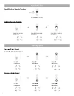
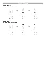
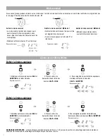
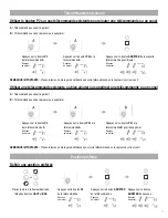
Page 3: ...roller Hold STOP on controller Approx Approx Motor Response Motor Response Motor Response Motor is now in step mode and ready for setting limits IMPORTANT IMPORTANT IMPORTANT OR SECS Approx JOG BEEP Set Limits To save upper limit hold UP and STOP Cycle shade up and down prior to setting limits tosettle fabric Moveshadetothedesiredhighestorlowest positionby pressingtheUPorDOWNbuttons on controller ...

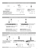
Page 4: ...on Consult user manual for your controller for information on selecting channel Damage to shade may occur when operating motor prior to setting limits Attention should be given Reversing motor direction using this method is only possible during initial set up Hold P1 button on motor head To check travel direction of shade press UP or DOWN on controller Quick Press Step Long Press Continuous Travel...

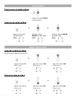
Page 5: ...and ready for setting limits IMPORTANT P JOG BEEP Pair motor with controller Consult user manual for your controller for information on selecting channel Hold P1 button on motor head Select channel on controller Hold STOP on controller Approx Motor Response Motor Response Motor is now in step mode and ready for setting limits IMPORTANT 5 INITIAL SET UP Pair motor with controller Check motor direct...

Page 6: ...ep mode and ready for setting limits IMPORTANT IMPORTANT IMPORTANT 5 INITIAL SET UP OR BEEP Reversing motor direction using this method is only possible during initial set up on o reverse shade direction hold both UP and DOWN Until the motor responds Hold STOP on controller Approx Approx Motor Response Motor Response ts IMPORTANT JOG BEEP ith controller direction for your tion on y occur when oper...

Page 7: ... on controller Quick Press Step Long Press Continuous Travel To reverse shade direction hold both UP and DOWN Until the motor responds Select channel on controller Hold STOP on controller Approx Approx Motor Response Motor Response Motor Response Motor is now in step mode and ready for setting limits IMPORTANT IMPORTANT IMPORTANT 5 INITIAL SET UP OR Pair motor with controller Check motor direction...

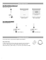
Page 8: ...otor direction Consult user manual for your controller for information on selecting channel Damage to shade may occur when operating motor prior to setting limits Attention should be given Reversing motor direction using this method is only possible during initial set up Hold P1 button on motor head To check travel direction of shade press UP or DOWN on controller Quick Press Step Long Press Conti...

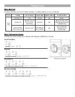
Page 9: ...tion None No Action If limits are set Operational control of motor run to limit Stop if running Motor Runs None Operational control of motor after pairing and limit setting is completed first time If motor is in Sleep Mode limits are set Wake and control Motor wakes and runs in a direction None Motor is restored from Sleep Mode and RF control is active Hold P1 button on motor head P1 button on mot...

Page 10: ...al control for each motor for programming purposes c Place all other motors into sleep mode ref to P1 function overview THE SHADE RAISES ON LOWERS UNEVENLY Check that the installation brackets are level and aligned Shim the brackets if necessary Shades are made of the highest quality materials for extended wear If it is not damaged or exposed to a great deal of direct sunlight it is not unrealisti...

Page 11: ...eur et extérieur Page 12 Configuration initiale Associer le moteur et la télécommande Page 13 Vérifier la direction du moteur Page 13 Définir les positions limites Page 13 Mode sommeil Page 14 Ajuster les positions limites Page 14 Télécommandes et canaux Page 15 Position préférée Pages 15 et 16 Ajuster la vitesse de fonctionnement Page 16 Configuration de l arrêt en douceur Page 17 Vérification de...

Page 12: ... extrémité sur les montants 3 Marquez ensuite la position du support et des trous de vis à l aide d un crayon à mine Servez vous de la mèche de 3 32 po pour percer les trous des vis REMARQUE IMPORTANTE Les supports doivent être de niveau et alignés les uns avec les autres REMARQUE IMPORTANTE Si vous installez les supports sur un mur en cloison sèche vous devez utiliser des chevilles et suivre les ...

Page 13: ... initial set up Hold P1 button on motor head To check travel direction of shade press UP or DOWN on controller Quick Press Step Long Press Continuous Travel To reverse shade direction hold both UP and DOWN Until the motor responds Select channel on controller Hold STOP on controller Approx Approx Motor Response Motor Response Motor Response Motor is now in step mode and ready for setting limits IM...

Page 14: ...etting limits motor will automatically exit from initial set up mode To save lower limit hold DOWN and STOP Motor Response Approx IMPORTANT IMPORTANT Pair motor with controller Check motor direction Consult user manual for your controller for information on selecting channel Damage to shade may occur when operating motor prior to setting limits Attention should be given Reversing motor direction u...

Page 15: ... UP or ntroller Travel To reverse shade direction hold both UP and DOWN Until the motor responds Hold STOP on controller Approx Approx Motor Response Motor Response Motor Response p mode and ready for setting limits IMPORTANT P VIBRATION BIP Pair motor with controller Consult user manual for your controller for information on selecting channel Hold P1 button on motor head Select channel on control...

Page 16: ...ct channel on controller Hold STOP on controller Approx Approx Motor Response Motor Response Motor Response Motor is now in step mode and ready for setting limits IMPORTANT IMPORTANT IMPORTANT 5 INITIAL SET UP OR BIP Reversing motor direction using this method is only possible during initial set up on o reverse shade direction hold both UP and DOWN Until the motor responds Hold STOP on controller ...

Page 17: ... of shade press UP or DOWN on controller Quick Press Step Long Press Continuous Travel To reverse shade direction hold both UP and DOWN Until the motor responds Select channel on controller Hold STOP on controller Approx Approx Motor Response Motor Response Motor Response Motor is now in step mode and ready for setting limits IMPORTANT IMPORTANT IMPORTANT 5 INITIAL SET UP OR Pair motor with contro...

Page 18: ...or Response Motor is now in step mode and ready for setting limits IMPORTANT IMPORTANT IMPORTANT 5 INITIAL SET UP OR Pair motor with controller Check motor direction Consult user manual for your controller for information on selecting channel Damage to shade may occur when operating motor prior to setting limits Attention should be given Reversing motor direction using this method is only possible...

Page 19: ...l Feedback Audible Feedback Function Described Short Press If limit is NOT set None No Action None No Action If limits are set Operational control of motor run to limit Stop if running Motor Runs None Operational control of motor after pairing and limit setting is completed first time If motor is in Sleep Mode limits are set Wake and control Motor wakes and runs in a direction None Motor is restor...

Page 20: ...e moteur individuellement pour effectuer la programmation c Placez tous les autres moteurs en mode sommeil reportez vous aux instructions pour le bouton P1 LE STORE SE LÈVE OU S ABAISSE DE MANIÈRE INÉGALE Vérifiez que les supports sont de niveau et alignés l un avec l autre Au besoin ajoutez des cales d espacement C8 50 3500 rév 04 22 Les stores à enrouleur sont fabriqués avec des matériaux de qua...

Reviews: