2002 Buell P3: Engine
3-19
HOME
16. Install clutch cable at hand lever location. See
6.4
CLUTCH
.
17. Install drive belt. See
1.11 DRIVE BELT AND REAR
SPROCKET
.
18. Install front sprocket cover. See
2.22 SPROCKET
COVER
.
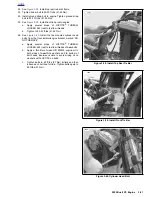
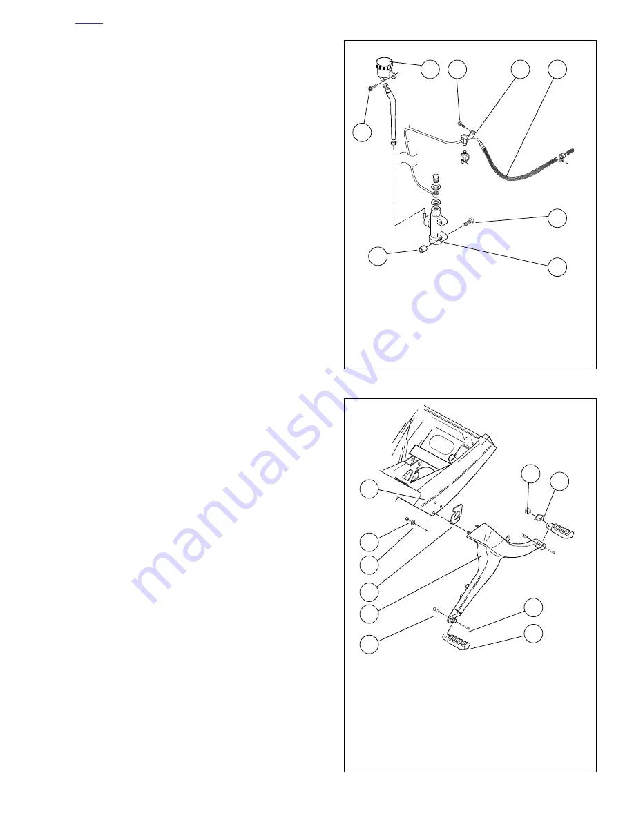
19. Install master cylinder onto footpeg bracket. See
2.21
FOOTPEGS AND FOOTPEG SUPPORT BRACKETS
.
a. Apply several drops of LOCTITE
®
THREAD-
LOCKER 243 (blue) to last few threads.
b.
Tighten to 4-6 ft-lbs (5-8 Nm).
NOTE:
SEE TOP END ASSEMBLY SECTION. The steps mentioned
previously complete Assembly preparation for top end servic-
ing. You may now proceed with TOP END ASSEMBLY PRO-
CEDURES. Then proceed to step 22.
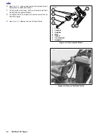
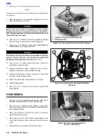
Figure 3-32. Brake Line Assembly
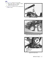
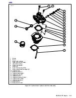
Figure 3-33. Footpeg Bracket Assembly
1.
Screw
2.
Brake Fluid Reservoir
3.
Screw
4.
Brake Line Bracket
5.
Screw
6.
Brake Line
7.
Master Cylinder
8.
Spacer
1
3
6
7
8
2
5
4
a0017x3x
1.
Frame
2.
Locknut
3.
Washer
4.
Spacer
5.
Footrest Support Bracket
6.
Clevis Pin
7.
Footpeg
8.
Cotter Pin
9.
Index Plate
10. Spacer
a0016x3x
1
2
3
4
5
6
8
7
10
9
Summary of Contents for 2002 P3
Page 2: ......
Page 17: ...A 15 Appendix A Tools HOME ...
Page 32: ...C 3 Appendix C Metric Conversions HOME ...
Page 41: ...1 8 2002 Buell P3 Maintenance HOME NOTES ...
Page 75: ......
Page 111: ...2 36 2002 Buell P3 Chassis HOME NOTES ...
Page 143: ...2 68 2002 Buell P3 Chassis HOME NOTES ...
Page 144: ...2002 Buell P3 Chassis 2 69 HOME ...
Page 146: ......
Page 147: ......
Page 223: ...3 76 2002 Buell P3 Engine HOME NOTES ...
Page 225: ......
Page 256: ...2002 Buell P3 Fuel System 4 31 HOME ...
Page 258: ......
Page 259: ......
Page 279: ...5 20 2002 Buell P3 Electric Starter HOME NOTES ...
Page 281: ......
Page 327: ......
Page 398: ...2002 Buell P3 Electrical 7 71 HOME ...
Page 400: ...Product 1 2 ...

