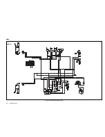
Appendix B: Wiring
B-1
HOME
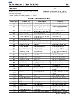
ELECTRICAL CONNECTORS
B.1
GENERAL
The following table provides a description of the connectors
found on your motorcycle.
Connector numbers are listed in [brackets] in this manual.
NOTE
Male ends of connectors are labeled “A” in text.
Female ends of connectors are labeled “B” in text.
Table B-1. Electrical Connectors
CONNECTOR
DESCRIPTION
COMPONENT(S)
LOCATION
[7]
6-place Amp Multilock
Tail Lamp/Rear Directionals
Under Seat
[10]
6-place Deutsch
Integrated Ignition Module Sensor
Left side of frame backbone on
T-stud
[22]
4-place Amp Multilock
Right Handlebar Switch Housing-
ignition power, module and starter
Behind windscreen
[20]
12-place Deutsch
Indicators/Speedometer
Behind windscreen
[24]
10-place Amp Multilock
Left Handlebar Switch Housing-
turn signals, lights
Behind windscreen
[30]
3-blade relay connector
Flasher Relay
Under seat, to right of battery
[33]
4-place Deutsch
Ignition/Headlamp Key Switch
Behind windscreen
[38]
4-place Amp Multilock
Headlamp
Behind windscreen/headlamp
[39]
12-place Packard
Speedometer/Indicators
On back of speedometer
[46]
2
-
place barrel connector
Voltage Regulator
Above swingarm, left side
[60]
2-place Amp Multilock
Side Stand Switch
On top of swingarm, cable tied to
rear brake line
[61]
9-slot fuse block
Fuse Block
Under seat on right side
[65]
3-place Deutsch
Speed Sensor
Under seat, to right of shock
[83]
3-place Amp Multilock
Ignition Coil
Under frame backbone at coil
[88]
6-place Deutsch
Throttle Position Sensor and Auto-
Enrichener
Under frame backbone, right side
[95]
2-place Amp Multilock
Clutch Switch
At left handlebar
[120]
Post
Oil Pressure Switch
Above oil filter, right lower side of
crankcase
[121]
2 blades
Rear Stoplight Switch
At switch, under frame by shock
absorber
[122]
Blade
Horn
At horn, behind front fork
[123]
4-blade relay connector
Starter Relay
Under seat to right of battery
[128]
Blade
Starter
Under starter solenoid
[131]
Post
Neutral Switch
Behind sprocket cover, right side
[134]
3-place Packard
Bank Angle Sensor
Under Seat to right of battery
[170]
2 blades
Front Brake Switch
At right handlebar switch
[171]
4-blade relay connector
System Relay
Under seat, to left of battery
[172]
1-Place Bullet
Neutral Switch to main harness
Above sprocket cover, right side
Summary of Contents for 2002 P3
Page 2: ......
Page 17: ...A 15 Appendix A Tools HOME ...
Page 32: ...C 3 Appendix C Metric Conversions HOME ...
Page 41: ...1 8 2002 Buell P3 Maintenance HOME NOTES ...
Page 75: ......
Page 111: ...2 36 2002 Buell P3 Chassis HOME NOTES ...
Page 143: ...2 68 2002 Buell P3 Chassis HOME NOTES ...
Page 144: ...2002 Buell P3 Chassis 2 69 HOME ...
Page 146: ......
Page 147: ......
Page 223: ...3 76 2002 Buell P3 Engine HOME NOTES ...
Page 225: ......
Page 256: ...2002 Buell P3 Fuel System 4 31 HOME ...
Page 258: ......
Page 259: ......
Page 279: ...5 20 2002 Buell P3 Electric Starter HOME NOTES ...
Page 281: ......
Page 327: ......
Page 398: ...2002 Buell P3 Electrical 7 71 HOME ...
Page 400: ...Product 1 2 ...

