7-70
2002 Buell P3: Electrical
HOME
18. See
Figure 7-95.
Mate ignition module connector [10]
and attach to T-stud on left side of frame backbone.
19. Feed longer bundle at front through frame hole to left
side of motorcycle. Attach harness to T-stud.
20. Hook right side of harness to two T-studs on right side of
motorcycle.
21. Mate right handlebar switch connector [22], front brake
lamp switch connector [170]. Secure wires with cable
ties.
22. Mate left handlebar switch connector [24] and clutch
switch connector [95]. Secure wires with cable ties.
23. Connect speedometer connector [39].
24. Mate ignition switch connector [33].
25. Install left and right front turn signal bullet connectors as
marked during removal.
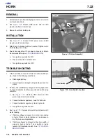
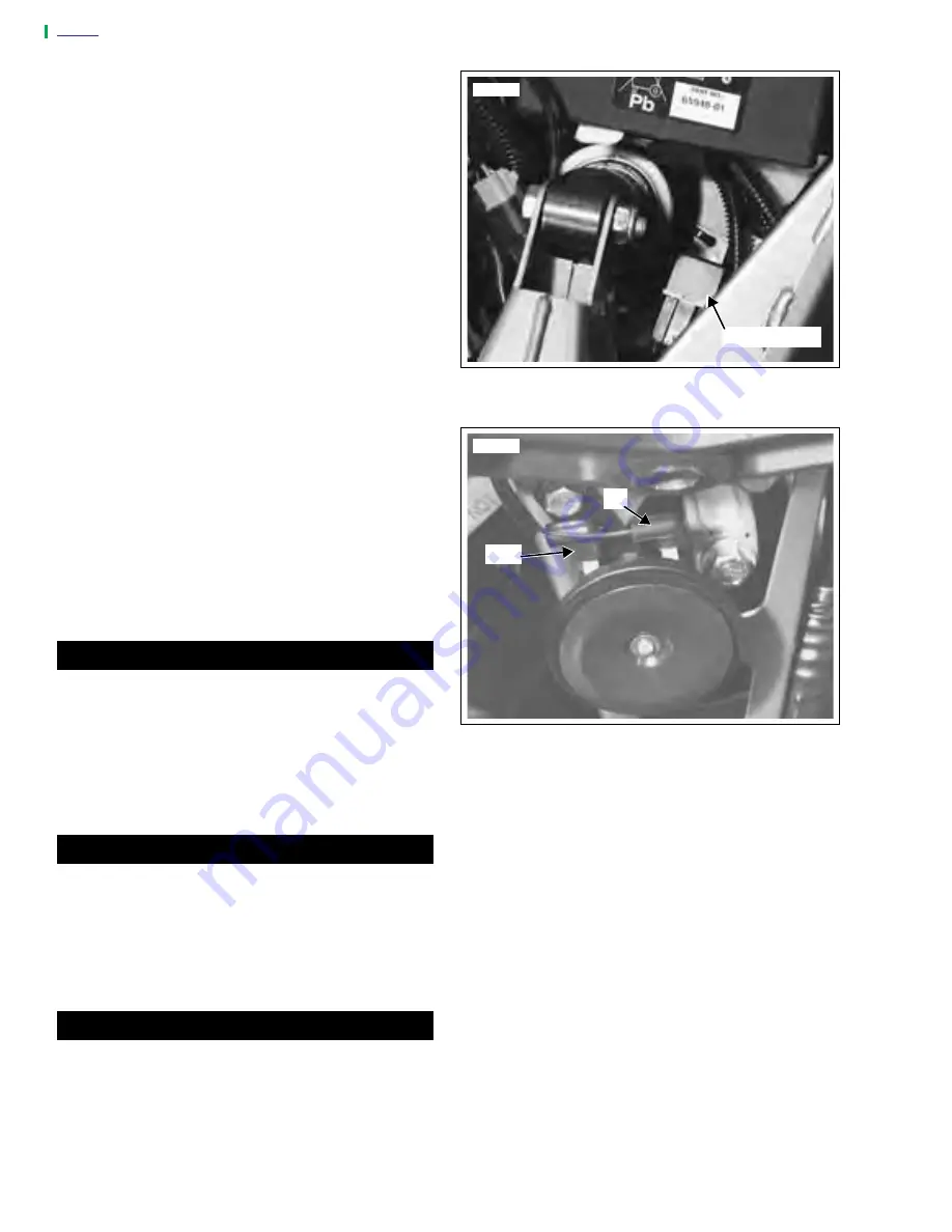
26. See
Figure 7-102.
Feed horn wires through frame hole
on right side and install connector [122] to horn. Cable
tie wires to isolator mount.
27. Cable tie main wiring harness to frame backbone with
three cable ties.
28. Connect headlamp connector [38] and install headlamp
housing. See
7.17 HEADLAMP
.
29. Install windscreen with four screws and washers. See
2.26 WINDSCREEN
.
30. Install fuel tank.
4.2 FUEL TANK COVER/FUEL TANK
.
1
1
WARNING
1
WARNING
Always connect the positive battery cable first. If the
positive cable should contact ground with the negative
cable installed, the resulting sparks could cause a bat-
tery explosion which could result in serious injury or
death.
31. Install battery and reconnect battery cables, positive
cable first. See
7.16 BATTERY
.
1
1
WARNING
1
WARNING
After installing seat, pull upward on front of seat to be
sure it is locked in position. If seat is loose, it could shift
during vehicle operation and startle the rider, causing
loss of control which could result in death or serious
injury.
32. Install seat. See
2.28 SEAT
.
1
1
WARNING
1
WARNING
Check for proper tail lamp, turn signal and headlamp
operation before riding motorcycle. Visibility is a major
concern for motorcyclists. Failure to have proper tail
lamp, turn signal and/or headlamp operation could result
in death or serious injury.
33. Check for proper operation of headlamp, turn signals,
brake lamp and starting, charging and ignition systems.
Figure 7-101. System Relay
Figure 7-102. Horn Connector [122]
7815
System Relay
Y/BK
BK
7816
Summary of Contents for 2002 P3
Page 2: ......
Page 17: ...A 15 Appendix A Tools HOME ...
Page 32: ...C 3 Appendix C Metric Conversions HOME ...
Page 41: ...1 8 2002 Buell P3 Maintenance HOME NOTES ...
Page 75: ......
Page 111: ...2 36 2002 Buell P3 Chassis HOME NOTES ...
Page 143: ...2 68 2002 Buell P3 Chassis HOME NOTES ...
Page 144: ...2002 Buell P3 Chassis 2 69 HOME ...
Page 146: ......
Page 147: ......
Page 223: ...3 76 2002 Buell P3 Engine HOME NOTES ...
Page 225: ......
Page 256: ...2002 Buell P3 Fuel System 4 31 HOME ...
Page 258: ......
Page 259: ......
Page 279: ...5 20 2002 Buell P3 Electric Starter HOME NOTES ...
Page 281: ......
Page 327: ......
Page 398: ...2002 Buell P3 Electrical 7 71 HOME ...
Page 400: ...Product 1 2 ...

