3-54
2004 Buell Lightning: Engine
HOME
PROCEDURE FOR USING THE
NEWAY VALVE SEAT CUTTER
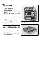
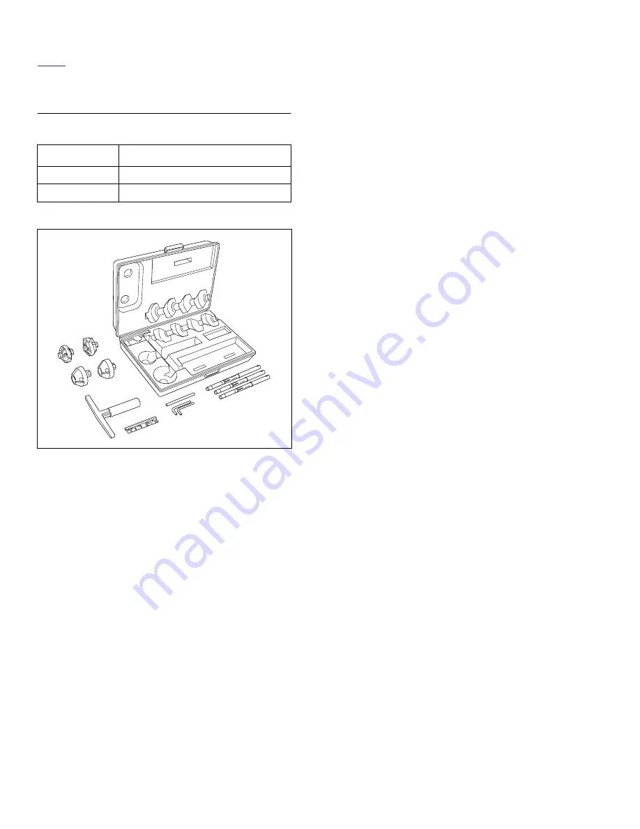
Table 3-19. Neway Valve Seat Cutter
NOTE
●
Verify correct valve stem to valve guide clearance before
refacing. See
Table 3-18.
If new guides must be
installed, complete that task before refacing valves and
seats.
●
This procedure is not based on the lapping of valves. The
end result is an interference fit between the valve of 45°
and the valve seat which will be 46°.
1.
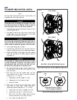
Secure cylinder head for service.
a. Thread 12 mm end of CYLINDER HEAD HOLDING
FIXTURE (Part No. HD-39786) into cylinder head
spark plug hole.
b.
Clamp tool in vise and further tighten cylinder head
onto the fixture to prevent any movement during
operation.
c.
Place cylinder head at a 45° angle or one that offers
a comfortable working position.
2.
Obtain the NEWAY VALVE SEAT CUTTER SET (HD-
35758A) and cut valve seat angle to 46°. Do not remove
any more metal than is necessary to clean up the seat
(that is, to provide a uniform finish and remove pitting).
3.
In order to determine the correct location of the 46° valve
seat in the head, measure the width of the valve to be
used and subtract 0.080" (2.032 mm) from that number.
4.
Set your dial caliper to the lesser measurement and lock
down for quick reference. This is the location of your
valve seat.
5.
Use a permanent magic marker to highlight the valve
seat area that is going to be cut and be sure to highlight
all 3 angles. Allow marker to dry before proceeding.
NOTE
●
Always ensure cutter blades and cutter pilot are clean
before beginning the cutting process. The correct clean-
ing brush is supplied with the Neway tool set.
●
Also ensure the inside of the valve guide is clean by
using Kent-Moore cleaning brush (Part No. HD-34751).
6.
Choose the cutter pilot that fits properly into the valve
guide hole and securely seat the pilot by pushing down
and turning using the installation tool supplied in the tool
set.
7.
Choose the proper 46° cutter (intake or exhaust) and
gently slide the cutter onto the pilot being careful not to
drop the cutter onto the seat.
8.
While applying a constant and consistent pressure,
remove just enough material to show a complete clean-
up on the 46° angle.
NOTES
●
If the width of the clean-up angle is greater on one side
of the seat than the other, the guide may need to be
replaced due to improper installation.
●
After making the 46° cut, if you discover a groove cut
completely around the seat this means the blades of the
cutter are in alignment and need to be staggered. This is
accomplished by loosening all of the blades from the cut-
ter body and moving each blade slightly in it’s cradle in
opposite directions on the cutter. The tool needed to
loosen the blades is supplied in the tool set. A perma-
nent magic marker mark every 90° will help in determin-
ing where new angles are.
PART NO.
SPECIALTY TOOL
HD-35758A
Neway valve seat cutter
HD-39786
Cylinder head holding fixture
Figure 3-76. Neway Valve Seat Cutter
a0087x3x
Summary of Contents for 2004 XB9S
Page 2: ......
Page 35: ...D 2 2004 Buell Lightning Appendix D HOME Rear Brake Systems Top View b1115xbsx ...
Page 36: ...2004 Buell Lightning Appendix D D 3 HOME Rear Brake Systems Left Side View b1116xcsx ...
Page 44: ...2004 Buell Lightning Appendix D D 11 HOME Clutch Cable Right Side View b1124xasx ...
Page 47: ...HOME NOTES ...
Page 49: ......
Page 103: ......
Page 201: ...HOME NOTES ...
Page 203: ......
Page 275: ...HOME NOTES ...
Page 307: ...HOME NOTES ...
Page 311: ...HOME NOTES ...
Page 351: ...HOME NOTES ...
Page 441: ......
Page 463: ...HOME NOTES ...
Page 465: ......
Page 517: ...HOME NOTES ...
Page 519: ......
Page 595: ...HOME NOTES ...
Page 597: ......


