2004 Buell Lightning: Electrical
7-49
HOME
INSTALLATION
Front
1.
See
Figure 7-53.
Insert bullet connectors and wiring
through hole in front module.
2.
Install turn signal using lockwasher and jam nut. Tighten
fastener to 25-28 in-lbs (2.8-3.2 Nm).
3.
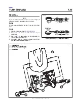
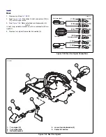
Attach bullet connectors on turn signal wires as shown in
Figure 7-57.
1
WARNING
1
WARNING
Check for proper turn signal operation before riding
motorcycle. Visibility is a major concern for motorcy-
clists. Failure to have proper turn signal operation could
result in death or serious injury.
4.
Check turn signals for proper operation. If operation fails,
reread procedure and verify that all steps were per-
formed.
a.
Turn ignition key switch to ON.
b.
Activate left turn signals using switch on left handle-
bar. Front and rear left turn signals must flash.
c. Activate right turn signals using switch on left han-
dlebar. Front and rear right turn signals must flash.
d.
Turn ignition key switch to OFF.
5.
Install windscreen. See
2.40 WINDSCREEN
.
Rear
1.
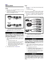
See
Figure 7-57.
Insert bullet connectors through center
tail section.
2.
Install reflector bracket.
NOTE
Be sure tab on turn signal fits into hole in reflector bracket
and tab on reflector bracket fits into hole in enter tail section.
3.
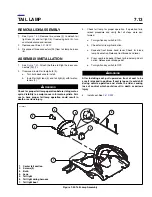
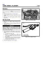
See
Figure 7-55.
Attach turn signal using lockwasher
and fastener (4).Tighten fastener to 25-28 in-lbs (2.8-3.2
Nm).
4.
Attach bullet connectors on turn signal wires as shown in
Figure 7-57.
1
WARNING
1
WARNING
Check for proper turn signal operation before riding
motorcycle. Visibility is a major concern for motorcy-
clists. Failure to have proper turn signal operation could
result in death or serious injury.
5.
Check turn signals for proper operation. If operation fails,
reread procedure and verify that all steps were per-
formed.
a.
Turn ignition key switch to ON.
b.
Activate left turn signals using switch on left handle-
bar. Front and rear left turn signals must flash.
c. Activate right turn signals using switch on left han-
dlebar. Front and rear right turn signals must flash.
d.
Turn ignition key switch to OFF.
1
WARNING
1
WARNING
After installing seat, pull upward on front of seat to be
sure it is locked in position. If seat is loose, it could shift
during vehicle operation and startle the rider, causing
loss of control which could result in death or serious
injury.
6.
Install seat. See
2.41 SEAT
.
Figure 7-56. Front Turn Signal Connections
2
2
1
1
1
1
2
2
[31B]
[31A]
[31B]
[31A]
b1100x7x
Right Turn
Signal
Left Turn
Signal
BK
V
BE
BK
BK
BE
BK
BN
Figure 7-57. Rear Turn Signal Connections
1
1
2
2
2
2
1
1
1
2
1
2
1
1
[19A]
[93A]
[93B]
[93B]
[93A]
[18A]
[18A]
[18A]
[18A]
[19A]
[19B]
[19B]
Right turn signal
Tail lamp
b1099x7x
Left turn signal
V
BK
BK
BN
Tail lamp ground
BK
O/W
R/Y
Summary of Contents for 2004 XB9S
Page 2: ......
Page 35: ...D 2 2004 Buell Lightning Appendix D HOME Rear Brake Systems Top View b1115xbsx ...
Page 36: ...2004 Buell Lightning Appendix D D 3 HOME Rear Brake Systems Left Side View b1116xcsx ...
Page 44: ...2004 Buell Lightning Appendix D D 11 HOME Clutch Cable Right Side View b1124xasx ...
Page 47: ...HOME NOTES ...
Page 49: ......
Page 103: ......
Page 201: ...HOME NOTES ...
Page 203: ......
Page 275: ...HOME NOTES ...
Page 307: ...HOME NOTES ...
Page 311: ...HOME NOTES ...
Page 351: ...HOME NOTES ...
Page 441: ......
Page 463: ...HOME NOTES ...
Page 465: ......
Page 517: ...HOME NOTES ...
Page 519: ......
Page 595: ...HOME NOTES ...
Page 597: ......

